
Rogers PCB and PTFE PCB are often compared in RF and microwave projects because both are used when standard FR4 cannot meet the signal loss, impedance stability, or high frequency performance requirements of the design.
But they are not the same type of comparison. Rogers is a material brand with several high frequency laminate families. PTFE is a material category. Some Rogers materials are PTFE-based, while others are not. So the real question is not simply “Rogers or PTFE?” It is: which material system fits the working frequency, loss target, stackup, processing difficulty, and production budget of this board?
For buyers, this distinction matters. A material may look correct in the quotation stage but create problems later if the drilling, plating, lamination, or controlled impedance PCB design review is not done properly.
Quick Summary
Rogers PCB is commonly used in RF PCB, microwave PCB, antenna PCB, radar electronics, wireless communication boards, satellite communication, and high frequency test equipment.
PTFE PCB is often reviewed for low-loss microwave circuits, radar signal paths, antenna systems, aerospace RF boards, and demanding high frequency applications.
Rogers materials may offer a wider selection of high frequency laminate options, while PTFE-based materials are often chosen when low dielectric loss and stable microwave behavior are key concerns.
The better choice depends on frequency, Dk, Df, board thickness, copper thickness, stackup structure, controlled impedance target, manufacturing difficulty, and cost.
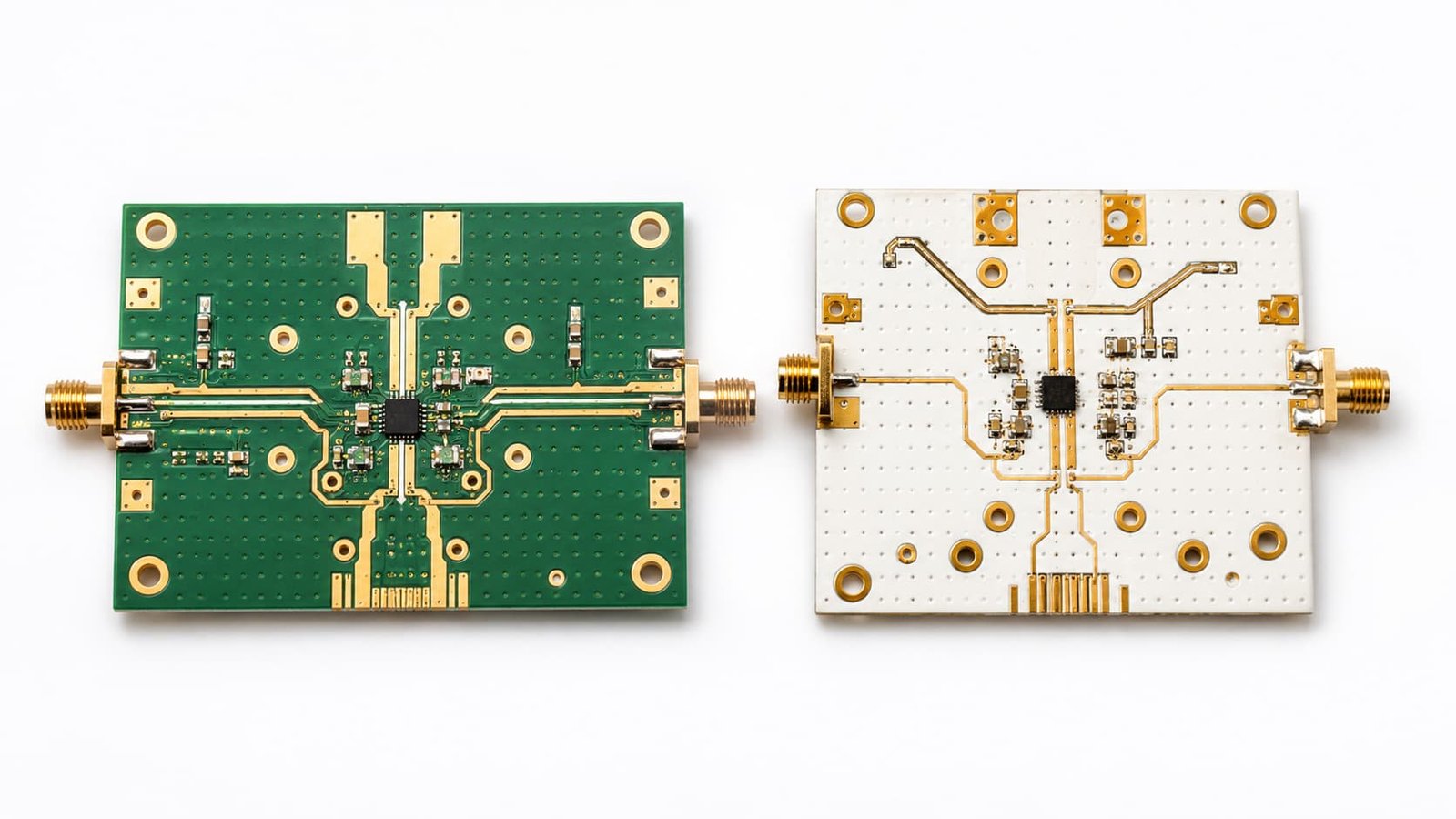
Rogers PCB: What Buyers Usually Expect
When buyers ask for Rogers PCB, they usually expect a stable high frequency material with known RF performance and strong industry acceptance.
Common applications include:
RF modules
Microwave circuits
Antenna PCBs
Radar electronics
Satellite communication
5G communication devices
Wireless infrastructure
Test and measurement equipment
The advantage of Rogers PCB is not only electrical performance. It is also the material system, availability, documentation, and supplier familiarity. Many engineers already know common Rogers material families such as RO4000 series, RO3000 series, and RT/duroid materials.
In real projects, Rogers materials are often selected when the buyer wants a high frequency laminate that can be discussed clearly with engineers, PCB manufacturers, and end customers.
PTFE PCB: Where It Becomes Valuable
PTFE PCB is usually considered when the design needs low dielectric loss and stable high frequency behavior.
Typical applications include:
Microwave signal boards
Radar antenna circuits
Satellite communication boards
Aerospace RF electronics
High frequency test boards
Low-loss RF transmission paths
Precision antenna feed networks
PTFE materials can perform well in demanding RF and microwave environments, but they are usually more difficult to process than standard FR4. Drilling, hole wall preparation, plating, bonding, lamination, and dimensional control all need more manufacturing attention.
This is why PTFE PCB should not be selected only because it sounds “higher performance.” If the factory is not experienced with PTFE processing, the material advantage may be lost during production.
Key Difference: Material Brand vs Material Category
A common misunderstanding is treating Rogers PCB and PTFE PCB as two equal material names.
Rogers is a manufacturer and brand. Its product families include different types of high frequency laminates. Some use PTFE-based systems; some are designed for easier processing compared with traditional PTFE materials.
PTFE is the base polymer category. PTFE laminates can come from different suppliers and may have different fillers, reinforcement, copper types, thicknesses, and processing behavior.
This means a buyer should avoid writing only “Rogers or PTFE acceptable” without giving the real design requirement. The manufacturer still needs to know the working frequency, impedance target, loss requirement, board thickness, stackup, and quantity.
Signal Loss and Frequency
Signal loss is usually the first reason buyers compare Rogers PCB and PTFE PCB.
At lower RF frequencies, several high frequency materials may work. As the frequency increases, dielectric loss, copper roughness, trace geometry, via transitions, and connector areas become more visible in testing.
PTFE-based materials are often reviewed when low loss is a top priority. Rogers materials may also provide low-loss options depending on the selected laminate family.
But material alone does not decide signal loss. The full RF path matters:
Trace length
Dielectric thickness
Copper type
Surface finish
Via transitions
Connector launch
Ground reference
Stackup tolerance
Manufacturing repeatability
A strong laminate cannot fully compensate for poor layout or weak grounding.
Stackup and Impedance Review
Both Rogers PCB and PTFE PCB projects usually need proper stackup review.
The stackup should confirm:
Material type
Layer count
Dielectric thickness
Copper thickness
RF signal layer
Ground plane
Final board thickness
Controlled impedance target
Surface finish
Via structure
Hybrid material requirement
Controlled impedance depends on material Dk, dielectric thickness, trace width, copper thickness, and reference plane structure. If the material or dielectric thickness changes during production, the impedance may shift.
This is why impedance should be calculated based on the real production stackup, not only the early design assumption.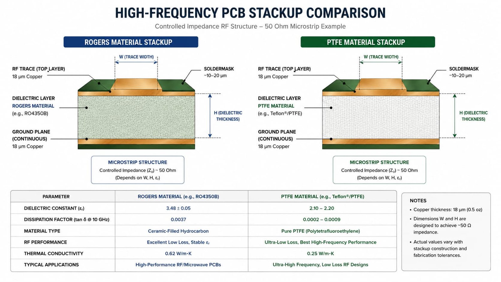
Manufacturing Difficulty
Manufacturing is where Rogers PCB and PTFE PCB can become very different.
Some Rogers materials are designed with practical PCB processing in mind. Depending on the material family, the fabrication process may be closer to standard PCB production than traditional PTFE laminates.
PTFE PCB usually requires more process control. The material can be softer and more difficult to drill cleanly. Hole wall preparation and plating reliability need careful review. In multilayer or hybrid designs, lamination and dimensional stability become even more important.
Manufacturing points to review include:
Drilling quality
Plated through-hole reliability
Hole wall preparation
Copper adhesion
Etching accuracy
Dimensional stability
Lamination behavior
Surface finish
Final inspection
For buyers, this affects both prototype success and batch production stability.
Antenna PCB Considerations
Antenna PCB projects are sensitive to material selection.
Dk affects antenna size, resonant behavior, feed line geometry, and impedance matching. Df affects signal loss and antenna efficiency. Board thickness and copper pattern accuracy also affect the final result.
Both Rogers and PTFE materials may be considered for antenna PCB. The better choice depends on:
Operating frequency
Antenna structure
Feed line impedance
Board thickness
Copper tolerance
Ground plane design
Testing requirement
Production quantity
Material substitution should not be made casually in antenna projects. Even if two materials look similar on paper, the final antenna behavior may change.
Radar and Microwave PCB Considerations
Radar and microwave PCB projects usually care more about low loss, phase stability, via transitions, connector launches, and repeatable testing.
PTFE materials are often reviewed for demanding microwave signal paths. Rogers materials are also widely used in radar and microwave applications, depending on the selected material family.
For these boards, buyers should not compare only laminate cost. They should compare total project risk:
Will the material be available for batch production?
Can the factory drill and plate it reliably?
Can impedance be controlled with the selected thickness?
Will the surface finish match the RF and assembly requirements?
Can prototype results be repeated in batch production?
The lowest material price is not always the lowest project cost.
Procurement and Cost Review
From a procurement point of view, Rogers PCB and PTFE PCB should be compared by both price and risk.
Important cost-related factors include:
Material cost
Material availability
Panel utilization
Prototype lead time
Batch repeatability
Processing difficulty
Scrap risk
Testing requirement
Supplier experience
A PTFE material may provide strong RF performance, but if the process risk is high, the final cost may increase. A Rogers material may be easier to specify and communicate, but the selected grade still needs to match the RF requirement.
For serious RF and microwave projects, procurement should work together with engineering instead of choosing material by quotation price alone.
What Buyers Should Send for Quotation
To compare Rogers PCB and PTFE PCB properly, buyers should prepare:
Gerber files
Drill files
PCB stackup
Material preference
Working frequency
Board thickness
Copper thickness
Surface finish
Controlled impedance requirement
Quantity
Prototype or batch plan
Application background
If the material is not fixed, the application background is very useful. A manufacturer can only suggest a practical material when the RF requirement is clear.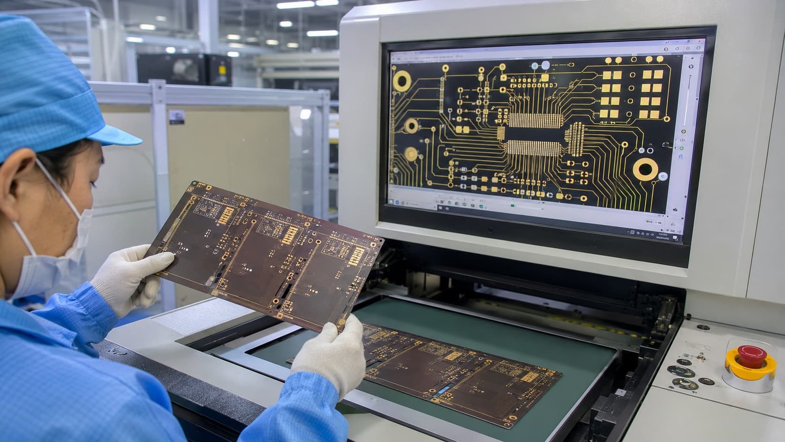
Common Mistakes to Avoid
Common mistakes include:
Treating Rogers and PTFE as simple interchangeable options
Choosing material only by price
Providing Gerber files without stackup
Missing controlled impedance details
Changing material after layout is complete
Ignoring drilling and plating risk
Not considering prototype-to-batch repeatability
Selecting surface finish without RF or assembly review
Not explaining the working frequency or application
These mistakes often do not appear during visual inspection. They appear during RF testing, assembly, or batch production.
Conclusion
Rogers PCB and PTFE PCB can both be strong choices for RF and microwave applications, but they serve different project needs.
Rogers PCB is often selected for known high frequency material systems, broad engineering acceptance, and practical RF PCB manufacturing. PTFE PCB is often reviewed when the design needs low-loss microwave behavior and stable high frequency performance, but it usually requires more careful process control.
The best choice depends on working frequency, signal loss target, stackup, controlled impedance, drilling, plating, surface finish, availability, and production risk. For buyers, the right decision is not the most expensive material or the most familiar name. It is the material that can meet the RF requirement and be manufactured reliably.