FR4 + Rogers hybrid PCB stackup is used when a circuit needs high frequency performance in critical RF or microwave areas, but does not need Rogers material across the entire board. In this structure, Rogers material is usually used for RF signal layers, antenna feed lines, microwave circuits, or controlled impedance paths, while FR4 is used for supporting layers, digital circuits, power layers, or mechanical structure.
For many B2B PCB projects, a hybrid stackup can be a practical way to balance RF performance, cost control, board rigidity, layer count, and manufacturing feasibility.
However, FR4 + Rogers hybrid PCB is not a simple material mix. It requires careful engineering review because different materials may have different dielectric properties, thermal expansion behavior, bonding requirements, lamination response, and drilling characteristics.
Quick Summary
FR4 + Rogers hybrid PCB stackup is useful when only part of the board requires high frequency performance.
Rogers material is commonly used for RF, microwave, antenna, radar, and controlled impedance layers, while FR4 can be used for digital, power, control, or supporting layers.
Hybrid stackups can reduce material cost and improve structural practicality, but they require careful stackup design, lamination control, impedance calculation, and material compatibility review.
For hybrid projects, Riching PCB supports Rogers PCB processing, FR4 + high frequency hybrid PCB manufacturing, RF PCB fabrication, microwave PCB manufacturing, antenna PCB production, and controlled impedance PCB review. Riching PCB’s Rogers materials page also mentions Rogers + FR4 hybrid stackups as a way to balance RF performance, structural support, and production cost.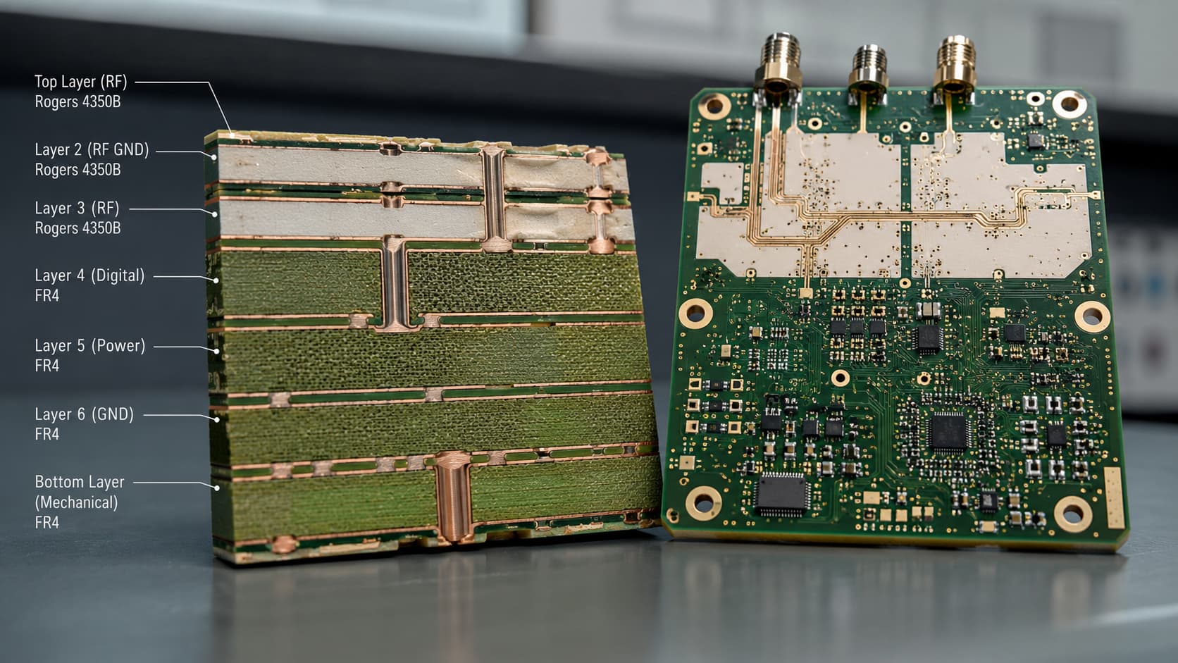
What Is an FR4 + Rogers Hybrid PCB Stackup?
An FR4 + Rogers hybrid PCB stackup combines Rogers high frequency material with FR4 material in one multilayer PCB structure.
The goal is usually to place Rogers material only where high frequency performance matters most. These areas may include RF transmission lines, microwave signal paths, antenna feed lines, filters, RF front-end circuits, or radar signal layers.
FR4 can be used in other layers where the circuit does not require low-loss RF performance. These areas may include power distribution, digital control, connectors, mechanical support, or low-speed circuits.
This approach is common in projects where the board has both RF and non-RF functions.
Typical hybrid PCB applications include:
RF communication modules
Microwave communication boards
Antenna systems
Radar electronics
5G communication devices
Wireless infrastructure
Test and measurement equipment
Industrial RF equipment
Why Use Rogers and FR4 Together?
To Reduce Material Cost
Using Rogers material across the entire PCB can increase material cost, especially in larger multilayer boards.
If only one or two layers carry RF or microwave signals, it may not be necessary to use Rogers material for every layer. A hybrid structure allows the design to use Rogers material in critical signal areas and FR4 in less sensitive areas.
This can make the project more cost-effective while still supporting the required RF performance.
To Support Mixed RF and Digital Circuits
Many modern electronic products include both RF circuits and digital or power circuits.
For example, a wireless communication board may include antenna feed lines, RF front-end circuits, digital control, power management, connectors, and shielding areas on the same PCB.
In this case, Rogers material may be used for the RF layer, while FR4 may support the digital and power sections.
To Improve Mechanical Structure
FR4 can provide practical mechanical support for multilayer boards.
Some high frequency materials may have different rigidity, thickness options, or processing behavior compared with standard FR4. Using FR4 in part of the stackup can help improve board structure, reduce unnecessary material use, and support common assembly requirements.
To Simplify Some Manufacturing Decisions
Rogers RO4000 series materials are often selected because they offer high frequency performance with relatively practical PCB processing. Rogers’ processing guidelines state that RO4003C, RO4350B, and RO4835 laminates can be processed through develop, etch, and strip systems typically used for FR4 materials. The same guidelines also cover double-sided and multilayer boards using these materials.
This does not mean hybrid PCB is easy, but it does mean some Rogers materials are designed with manufacturability in mind.
When Should You Use FR4 + Rogers Hybrid PCB?
When RF Layers Are Limited
Hybrid stackup is useful when only specific layers require high frequency performance.
For example, a 6-layer board may use Rogers material for the top RF layer and a nearby ground reference, while the remaining internal layers use FR4 for power, digital control, or mechanical support.
This is common in RF modules, antenna PCBs, and mixed-signal communication boards.
When Controlled Impedance Is Critical Only in Certain Areas
Some designs require controlled impedance only on RF feed lines, microwave paths, or antenna circuits.
If the controlled impedance paths are limited to specific layers, a hybrid stackup can focus high frequency materials where they matter most.
Controlled impedance still needs careful calculation. Material Dk, dielectric thickness, copper thickness, trace width, solder mask, and reference plane structure must be confirmed before production.
When the Board Combines RF and Non-RF Functions
Many wireless devices, radar modules, and communication boards are not purely RF circuits.
They may include MCU control, power management, digital interfaces, connectors, amplifiers, filters, antennas, and shielding structures.
A hybrid stackup helps separate critical RF performance areas from general circuit areas.
When Cost and Performance Must Be Balanced
For B2B buyers, the best material is not always the most expensive material.
A fully Rogers board may be unnecessary for some designs. A standard FR4 board may not provide enough RF performance. A hybrid PCB stackup can be the middle option.
It allows the project to keep RF performance in key areas while avoiding unnecessary material cost in non-critical layers.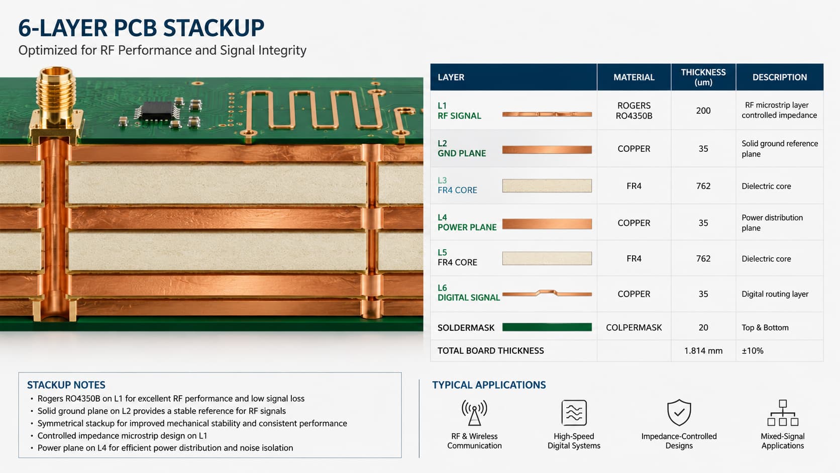
Key Design Factors for Hybrid PCB Stackup
Material Compatibility
Material compatibility is one of the most important issues in hybrid PCB manufacturing.
Rogers materials and FR4 materials may respond differently during lamination, drilling, plating, and thermal cycling. The manufacturer must review whether the selected materials, prepregs, bondply, and lamination process are suitable for the design.
Rogers’ processing documents note that RO4003C, RO4350B, and RO4835 laminates are compatible with many thermosetting and thermoplastic adhesive systems, and adhesive system guidelines should be consulted for bond cycle parameters.
Stackup Symmetry
Stackup symmetry can affect board flatness and dimensional stability.
If the stackup is unbalanced, the PCB may have higher risk of warpage. This is especially important for multilayer hybrid boards, larger boards, thin boards, or boards with strict assembly requirements.
Before production, the manufacturer should review layer symmetry, material distribution, copper balance, final thickness, and lamination feasibility.
Impedance Calculation
Impedance calculation must be based on the real production stackup.
For hybrid PCBs, the Dk value of each material layer matters. If the RF layer uses Rogers material but the reference structure or dielectric thickness changes, the final impedance may shift.
For this reason, impedance should be calculated after confirming:
Rogers material type
FR4 material type
Dielectric thickness
Copper thickness
Reference plane
Trace width
Solder mask condition
Final stackup tolerance
Drilling and Plated Through Holes
Hybrid PCB stackups may include different material types in the same plated through hole.
This makes drilling quality, hole wall preparation, copper plating, and plated through-hole reliability important. Rogers’ processing guidelines include detailed drilling and PTH processing notes for RO4003C, RO4350B, and RO4835 laminates, including drill parameter ranges and PTH preparation considerations.
For RF and microwave applications, via quality can also affect electrical performance, especially near RF transitions, grounding vias, and antenna feed structures.
Lamination Control
Lamination is a key process in hybrid PCB manufacturing.
The manufacturer must control temperature, pressure, material flow, bonding quality, registration, and final thickness. For hybrid stackups, lamination control is especially important because different material systems may behave differently.
Rogers RO4000 LoPro processing guidance notes compatibility with RO4400 materials and many thermoset prepregs, while also recommending process controls such as pre-bake and proper bond parameters based on the adhesive system.
Common Applications of FR4 + Rogers Hybrid PCB
RF Communication Modules
RF communication modules often combine RF signal paths with digital control, power circuits, and connectors.
A Rogers layer can support RF signal transmission, while FR4 layers support control and power functions.
Antenna Systems
Antenna PCBs may use Rogers material for the antenna trace and feed line, while FR4 supports other circuit functions or mechanical structure.
For antenna PCB projects, material Dk, board thickness, copper geometry, and feed line impedance are especially important.
Radar Electronics
Radar boards may need low-loss microwave performance in specific signal areas.
A hybrid structure can use Rogers material for radar signal paths or antenna layers, while FR4 supports the rest of the board.
5G and Wireless Infrastructure
5G communication devices and wireless infrastructure may require high frequency layers, controlled impedance, power distribution, and digital control in one board.
Hybrid stackups can help balance these mixed requirements.
Test and Measurement Equipment
Test equipment often requires stable RF performance and repeatable signal transmission.
Hybrid stackups may be used when the board combines RF paths with supporting control circuitry.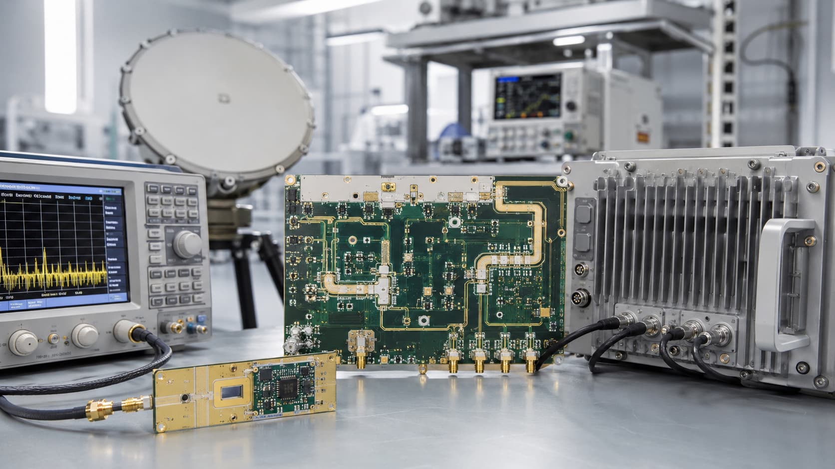
Manufacturing Checklist Before Production
Before producing an FR4 + Rogers hybrid PCB, the manufacturer should review:
Gerber files
Drill files
Full stackup
Rogers material type
FR4 material type
Bondply or prepreg system
Board thickness
Copper thickness
Controlled impedance target
Layer symmetry
Drill and via design
Surface finish
Quantity
Prototype or batch requirement
Application background
If the customer has not confirmed the material, the manufacturer should review whether the project really needs hybrid stackup or whether a simpler Rogers-only, FR4-only, or alternative high frequency material solution is better.
Conclusion
FR4 + Rogers hybrid PCB stackup is useful when a project needs high frequency performance only in selected RF, microwave, antenna, or radar areas while using FR4 for supporting, digital, power, or mechanical layers.
This structure can help balance performance and cost, but it requires careful review of material compatibility, stackup symmetry, impedance calculation, drilling, plating, lamination, and final reliability.
For RF modules, antenna systems, radar electronics, 5G devices, wireless infrastructure, and test equipment, working with an experienced high frequency PCB manufacturer can help confirm whether FR4 + Rogers hybrid PCB is the right choice before production.