RT/duroid PCB materials are used when a circuit needs stable microwave performance, low signal loss, and reliable high frequency behavior. These materials are often selected for microwave PCB, radar PCB, antenna systems, satellite communication, aerospace electronics, RF modules, and high frequency test equipment.
For many buyers, RT/duroid sounds like “just another Rogers material.” In practice, it is usually considered for more demanding RF and microwave projects where standard FR4 is not enough and where general-purpose high frequency laminates may still need closer review.
Rogers describes its RT/duroid laminates as filled PTFE composite materials for high reliability, aerospace, defense, RF, and microwave applications. For custom projects, Riching PCB supports Rogers materials, PTFE PCB manufacturing, microwave PCB manufacturing, and RF PCB manufacturing for high frequency circuit boards.
Quick Summary
RT/duroid materials are commonly used for microwave circuits, radar electronics, antenna systems, satellite communication, aerospace electronics, and high frequency signal transmission.
They are often chosen when the project needs low loss, stable Dk, controlled impedance, and better microwave performance than standard FR4.
RT/duroid PCB manufacturing needs careful review of stackup, drilling, plated through holes, lamination, dimensional stability, copper thickness, and surface finish.
Before quotation, buyers should prepare Gerber files, drill files, stackup, material requirement, controlled impedance details, board thickness, copper thickness, working frequency, and application background.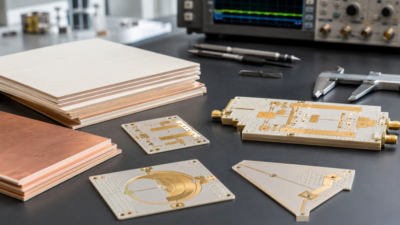
When Should You Consider RT/duroid Materials?
RT/duroid materials are not usually selected for simple control boards or low-cost electronic products. They are used when the circuit performance depends heavily on the laminate.
Typical situations include:
Microwave signal paths
Radar antenna boards
Satellite communication circuits
Aerospace RF electronics
High frequency test equipment
Low-loss transmission lines
RF front-end modules
Broadband communication circuits
For example, a standard FR4 board may be acceptable for a low-speed control section. But if the same product includes a microwave antenna feed, radar signal path, or satellite communication RF circuit, the RF layer may require a material with lower loss and more stable dielectric behavior.
This is why RT/duroid is often discussed together with microwave PCB, antenna PCB, and high frequency PCB projects.
RT/duroid 5870 and 5880: Low Dk, Low Loss Applications
RT/duroid 5870 and RT/duroid 5880 are two well-known materials in this family. Rogers describes RT/duroid 5880 laminates as glass microfiber reinforced PTFE composites with low dielectric constant and low dielectric loss, suitable for high frequency and broadband applications.
These materials may be reviewed for projects where low loss and stable microwave behavior are more valuable than the lowest material cost.
Common application areas include:
Broadband microwave circuits
Radar signal paths
Antenna feed networks
Satellite communication boards
High frequency test boards
Low-loss RF transmission structures
For projects that need a broader comparison between PTFE and Rogers material families, your article Rogers PCB vs PTFE PCB can support the same material decision flow.
What Makes RT/duroid Different from Standard FR4?
FR4 is practical, available, and widely used. But in microwave circuits, the board material can become part of the RF design.
RT/duroid materials are selected because they can offer lower loss and more stable high frequency characteristics than standard FR4 in demanding applications.
The difference matters in areas such as:
Insertion loss
Controlled impedance
Antenna tuning
Phase stability
Signal repeatability
Microwave transmission
High frequency test results
A design may look correct in Gerber files but still fail RF testing if the material loss, dielectric thickness, or impedance is not suitable. That is why material review should happen before production, not after the first prototype fails.
Stackup Review Before Manufacturing
The stackup is where most manufacturing risks become visible.
For RT/duroid PCB projects, the stackup should clearly define:
RT/duroid material type
Layer count
Dielectric thickness
Copper thickness
Ground plane location
RF signal layer
Controlled impedance target
Final board thickness
Surface finish
Via structure
Hybrid material structure if used
In RF and microwave PCB projects, stackup changes are not minor production adjustments. If dielectric thickness changes, impedance changes. If copper thickness changes, trace geometry and loss behavior can change. If the material is substituted, the finished board may no longer match the RF design.
For related manufacturing planning, RF PCB Stackup Design explains why stackup must be reviewed before production.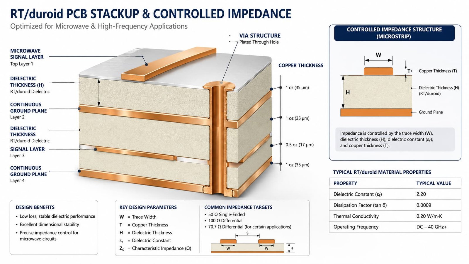
Drilling and Plated Through-Hole Review
Drilling is one of the areas where RT/duroid PCB projects need more attention.
PTFE-based materials can behave differently from FR4 during drilling and hole preparation. Poor drilling may lead to rough holes, poor surface activation, weak plating adhesion, or plated through-hole reliability issues.
Rogers provides fabrication guidelines for RT/duroid 5870/5880 high frequency circuit materials, including process notes for drilling, hole preparation, multilayer processing, and post-bond PCB processing.
In an RF or microwave board, vias are not only electrical connections. They may act as ground paths, signal transitions, via fences, connector grounds, or RF return paths. That makes drilling and plating quality part of the electrical performance.
Controlled Impedance and RF Performance
Most RT/duroid PCB projects require impedance review.
Controlled impedance depends on:
Material Dk
Dielectric thickness
Trace width
Copper thickness
Ground reference
Solder mask condition
Etching tolerance
Finished board thickness
For microwave and radar PCB projects, impedance error may cause reflection, mismatch, extra loss, or unstable test results. The manufacturer should calculate impedance based on the real production stackup, not only on the design idea.
If the project includes antenna feed lines, microwave filters, radar signal paths, or RF connectors, impedance should be confirmed before quotation and before fabrication.
Your technical article Why Controlled Impedance Matters in RF PCB Manufacturing can connect naturally with this topic.
Surface Finish Selection
Surface finish protects exposed copper and supports soldering or assembly. For RT/duroid PCB, the finish should be selected based on the assembly process and RF requirement.
Common options include:
ENIG
Immersion silver
OSP
HASL
Lead-free HASL
Hard gold for contact areas
Customer-specified finishes
ENIG is commonly used because it provides a flat surface and stable solderability. Immersion silver may be reviewed for some RF-sensitive applications. HASL should be used carefully in precision RF boards because surface flatness may not be ideal.
RT/duroid PCB Quotation Requirements
A good RT/duroid PCB quote needs more than Gerber files.
Buyers should prepare:
Gerber files
Drill files
PCB stackup
RT/duroid material requirement
Board thickness
Copper thickness
Surface finish
Controlled impedance requirement
Layer count
Quantity
Working frequency
Application background
Special reliability requirements
If the exact material is not confirmed, the working frequency and application background are very useful. The manufacturer can then review whether RT/duroid, RO4000 series, RO3000 series, PTFE, Taconic, F4B, or a hybrid stackup is the better option.

Common Mistakes to Avoid
The most common mistake is treating RT/duroid like a standard FR4 board.
Other mistakes include:
Missing stackup details
Unclear material specification
Changing material without RF review
Ignoring plated through-hole reliability
Not checking via transitions
No controlled impedance table
Choosing surface finish only by cost
Missing application background
No review of prototype-to-batch consistency
These issues can delay quotation, increase engineering back-and-forth, or create problems during RF testing.
Conclusion
RT/duroid PCB materials are used when microwave and RF performance matter more than the lowest material cost. They are suitable for demanding applications such as radar electronics, antenna systems, satellite communication, aerospace RF boards, microwave circuits, and high frequency test equipment.
To manufacture RT/duroid PCB reliably, the project should be reviewed around stackup, drilling, plated through holes, controlled impedance, copper thickness, lamination, surface finish, and final inspection.
For buyers, the best starting point is not only asking for a price. It is preparing complete files and giving the manufacturer enough RF context to review the board correctly before production.