The energy sector is increasingly RF-intensive. Smart grid infrastructure uses wireless communication for substation monitoring, demand response, and fault detection. Electric vehicle charging systems use RF for both wireless power transfer and communication protocols. Solar and wind installations use wireless telemetry for performance monitoring and grid management. Power converter systems use RF-isolated gate drivers and wireless feedback loops. Each of these applications has specific PCB material and manufacturing requirements that differ from consumer electronics.
As a direct high frequency PCB factory producing Rogers, F4B, and FR4 RF PCB for industrial and energy applications, we supply RF PCB for smart grid, EV charging, and power electronics programs. This guide covers the technical requirements for each major energy sector RF application.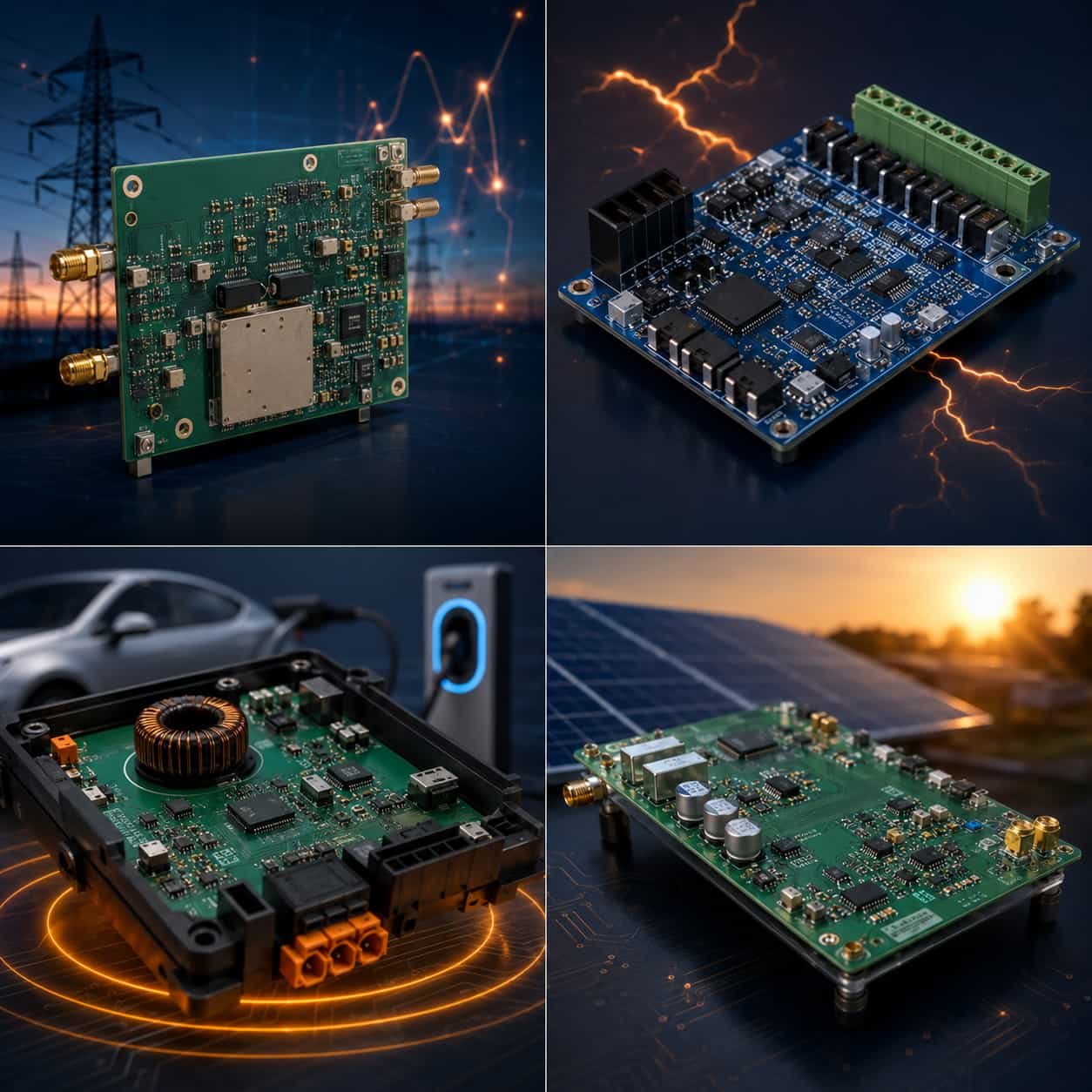
Quick Summary
Key point: Energy sector RF PCB applications span a wide frequency range from 85 kHz wireless EV charging through 915 MHz smart meter ISM band to 5.8 GHz substation WiFi. Material selection follows frequency — standard FR4 for sub-MHz wireless charging control, Rogers RO4350B for ISM band through 5.8 GHz smart grid applications. The defining characteristic of energy sector RF PCB compared to consumer electronics is the combination of RF performance requirements with wide operating temperature range (−40°C to +85°C outdoor), long service life (15–25 years), and often high-voltage isolation requirements.
Energy Sector RF PCB Applications
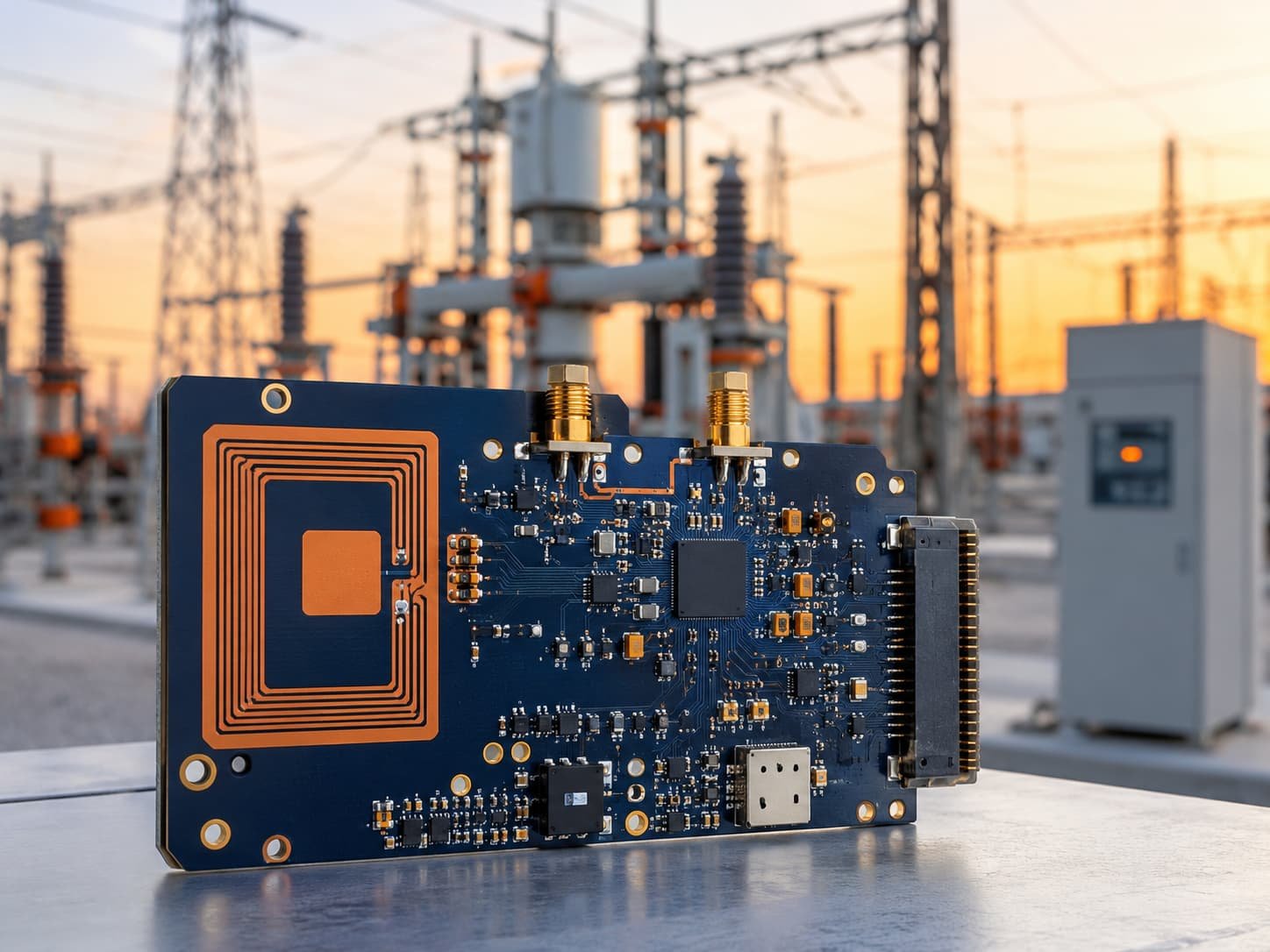
Smart Grid Communication PCB
Smart grid infrastructure uses RF communication at multiple frequency bands for different functions — from the sub-GHz mesh networks used for smart meter reading to the 5.8 GHz WiFi links used for substation control to the 900 MHz and 2.4 GHz protocols used for demand response and distribution automation.
- Smart metering (AMI): 868 MHz (Europe) / 915 MHz (US) — sub-GHz mesh network for meter reading
- Distribution automation: 900 MHz and 2.4 GHz — SCADA wireless links for feeder automation
- Substation WiFi: 2.4 GHz and 5.8 GHz — high-bandwidth communication between IEDs and control systems
- Power line carrier (PLC): 10–500 kHz — powerline communication for metering and load control
- WiSUN (IEEE 802.15.4g): 868/915 MHz — mesh networking standard for smart grid field devices
Material for Smart Grid RF PCB
- Sub-GHz (868/915 MHz): high-Tg FR4 — adequate at these frequencies, long outdoor service life
- 4 GHz smart grid wireless: Rogers RO4350B or F4BM220 — controlled impedance antenna feed
- 8 GHz substation WiFi: Rogers RO4350B 0.508mm — standard for 5.8 GHz industrial wireless
- Outdoor installation: Rogers RO4350B moisture absorption 0.06% — stable Dk in outdoor humidity
- Temperature: −40°C to +85°C outdoor rated — Rogers RO4350B Tg >280°C provides stable performance
- Service life: 15–25 years for smart grid infrastructure — IPC Class 3 recommended
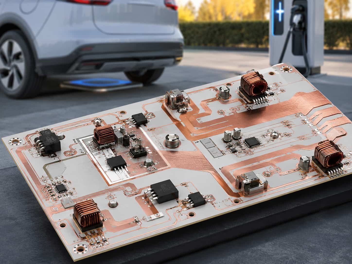
Wireless EV Charging PCB
Wireless (inductive) EV charging systems use magnetic resonance coupling to transfer power from the ground pad to the vehicle receiver without physical contact. The resonant frequency determines the PCB requirements at the power transfer stage, while the communication and control electronics use standard ISM band frequencies.
Power Transfer Stage PCB (85 kHz / 6.78 MHz)
- SAE J2954 standard (85 kHz): most common wireless EV charging frequency — sub-MHz
- AirFuel Alliance (6.78 MHz): higher frequency wireless charging for faster power transfer
- At 85 kHz: standard high-Tg FR4 or heavy copper FR4 for the inverter and resonator PCB
- At 6.78 MHz: Rogers RO4350B or F4B — needed for controlled impedance resonator coil PCB
- Copper weight: 2–6 oz for high-current resonator traces — confirm with factory for heavy copper capability
- Power level: 3.3 kW to 350 kW — PCB thermal management critical at high power
See: Heavy Copper High Frequency PCB
EV Charging Communication PCB (2.4 GHz / 5.8 GHz)
- Vehicle-to-grid (V2G) communication: 2.4 GHz or 5.8 GHz WiFi / DSRC
- Charging session management: ISO 15118 over powerline or wireless link
- Material: Rogers RO4350B for RF front-end at 2.4–5.8 GHz
- Temperature: automotive grade −40°C to +85°C — Rogers RO4350B adequate
- Certifications: automotive-grade PCB for vehicle-side components — IPC Class 2 minimum
Solar Inverter RF PCB
Solar inverters — both string inverters and central inverters for utility-scale solar farms — increasingly use wireless communication for monitoring, SCADA integration, and grid compliance. The RF PCB in these systems must operate reliably over the inverter’s 20–25 year service life in outdoor enclosures subject to wide temperature swings.
- Monitoring frequency: 915 MHz (US) / 868 MHz (Europe) for sub-GHz mesh telemetry
- WiFi monitoring: 2.4 GHz for local inverter dashboard and remote monitoring
- Grid communication: 5.8 GHz or licensed microwave for utility-scale solar farm SCADA
- Material: Rogers RO4350B for 2.4 GHz and 5.8 GHz monitoring PCB
- Service life: 20–25 years — IPC Class 3 recommended for long-life outdoor installation
- Temperature: −40°C to +85°C continuous outdoor operation
- Inverter interior temperature: can reach 70–80°C near power modules — Rogers RO4350B Tg >280°C handles this
Wind Turbine Communication PCB
Wind turbine monitoring and control systems use RF communication for blade pitch control, condition monitoring, and SCADA data transmission. The RF PCB in nacelle and hub electronics must survive the vibration, shock, and temperature cycling of wind turbine operation.
- Nacelle-to-hub wireless: 2.4 GHz for slip-ring-free pitch control communication
- Condition monitoring: 2.4 GHz or 5.8 GHz for vibration and temperature sensor data
- SCADA uplink: 900 MHz mesh or licensed microwave for farm-level data collection
- Material: Rogers RO4350B for 2.4–5.8 GHz applications
- Vibration rating: PCB must be designed for IEC 61400-1 wind turbine mechanical loads
- Temperature: −40°C to +85°C for nacelle electronics; lower for hub electronics in cold climates
Power Converter Gate Driver and Control PCB
High-frequency power converters — DC-DC converters, grid-tied inverters, motor drives — use RF-frequency signals in their gate driver circuits. As switching frequencies increase (SiC and GaN devices switch at 100 kHz–10 MHz), the gate driver PCB increasingly needs controlled impedance and low-loss materials.
- SiC MOSFET switching: 10 kHz–1 MHz — standard FR4 or high-Tg FR4 adequate
- GaN HEMT switching: 1–50 MHz — Rogers RO4350B for controlled impedance gate drive PCB
- RF-isolated gate driver: 6.78 MHz ISM or 13.56 MHz ISM — Rogers RO4350B for transformer PCB
- High-voltage isolation: controlled clearance and creepage on PCB — specify in design documentation
- Temperature: power module case temperatures can reach 85–125°C — Rogers RO4350B Tg >280°C adequate
Material Selection for Energy Sector RF PCB
Rogers RO4350B — Default for Energy RF Above 1 GHz
- 4 GHz smart grid wireless: standard choice — adequate Df, stable over outdoor temperature range
- 8 GHz substation WiFi: standard choice — 0.508mm substrate
- 78 MHz wireless EV charging resonator: adequate at 6.78 MHz for resonator coil PCB
- GaN gate driver at 1–50 MHz: adequate for controlled impedance gate drive PCB
- Solar/wind monitoring at 2.4–5.8 GHz: standard choice for long-life outdoor RF PCB
High-Tg FR4 — For Sub-MHz and Sub-GHz Energy Applications
- 85 kHz wireless EV charging: standard high-Tg FR4 adequate — very low frequency
- 868/915 MHz smart metering: high-Tg FR4 adequate at sub-GHz for typical trace lengths
- SiC gate driver at 10 kHz–1 MHz: high-Tg FR4 adequate for most designs
- Use high-Tg FR4 (Tg ≥ 150°C), not standard FR4 (Tg 130°C), for outdoor energy applications
Heavy Copper for High-Power RF PCB
Energy applications often combine RF performance requirements with high current carrying requirements — wireless EV charging resonators, power converter bus bars, solar inverter DC link. Heavy copper (2 oz, 3 oz, 4 oz) allows high current in the same PCB as RF traces.
- Wireless EV charging resonator: 2–4 oz copper for high-current resonator coil
- Gate driver PCB: 2 oz copper for low-impedance gate return path
- Heavy copper and RF: confirm minimum line width for RF traces at specified copper weight
- At 3 oz copper: minimum 50Ω microstrip trace width on RO4350B 0.508mm ≈ 0.95mm
See: Heavy Copper High Frequency PCB
Energy PCB Manufacturing Requirements
Wide Temperature Range and Long Service Life
- Operating temperature: −40°C to +85°C standard for outdoor energy electronics
- Rogers RO4350B Tg >280°C: stable dielectric properties over the full energy sector temperature range
- Dk temperature coefficient +50 ppm/°C: produces negligible Dk shift over −40°C to +85°C range for 2.4 GHz applications
- Service life 15–25 years: IPC Class 3 manufacturing recommended — 25 µm average PTH plating for via fatigue reliability
- Thermal cycling: energy electronics experience more daily thermal cycles than consumer electronics — IPC Class 3 via plating provides better fatigue life
High Voltage Isolation
Energy electronics PCB often carry both low-voltage RF signals and high-voltage power circuits on the same board. The PCB design must provide adequate electrical clearance and creepage between circuits at different voltage potentials.
- Clearance: minimum air gap between conductors at different voltage — IEC 60664-1 specifies by voltage and pollution degree
- Creepage: minimum surface distance along PCB between conductors — specified by working voltage and material group
- Rogers RO4350B: Material Group IIIb — confirm creepage requirements against IEC 60950 or IEC 61010 as applicable
- Solder mask: provides additional creepage distance — specify coverage requirements
- Slot isolation: PCB slots between high-voltage and low-voltage sections increase creepage
Conformal Coating for Outdoor Energy Applications
- Acrylic conformal coating: standard for most outdoor smart grid and solar/wind PCB
- Polyurethane: better chemical resistance for industrial environments
- Silicone: wide temperature range, suitable for high-temperature power electronics
- Specify conformal coating type and coverage at time of order
- Rogers RO4350B: compatible with standard conformal coatings — confirm with coating supplier
Controlled Impedance for Energy RF PCB
- Smart grid and monitoring wireless: ±10% impedance tolerance — standard for 2.4 GHz and 5.8 GHz
- GaN gate driver RF PCB: ±10% adequate for most gate drive frequencies
- Wireless EV charging resonator: resonator Q factor more sensitive to impedance — ±8% or better
- TDR verification: every production lot — same standard as commercial RF PCB
What to Specify for Energy Sector High Frequency PCB
- Application type: smart grid, EV charging, solar inverter, wind turbine, power converter
- Operating frequency — determines material selection
- Operating temperature range: −40°C to +85°C standard outdoor
- Service life: 15–25 years — specify IPC Class 3 for long-life applications
- Copper weight: standard 1 oz, or heavy copper (2–4 oz) for high-current sections
- High-voltage isolation requirements: clearance and creepage distances
- Conformal coating: type and coverage
- Material: Rogers RO4350B (standard for energy RF above 1 GHz), high-Tg FR4 (sub-GHz)
- Controlled impedance: target, tolerance, verification
- Quantity: prototype or production volume
For the complete quotation file checklist, see What Files Are Needed for a High Frequency PCB Quotation?. For factory capability, see China High Frequency PCB Manufacturer: Rogers, PTFE, Taconic Direct Factory.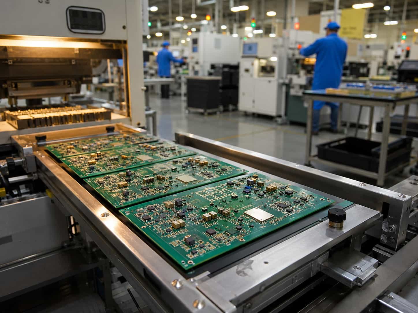
Conclusion
Energy and power electronics RF PCB spans from 85 kHz wireless EV charging through 5.8 GHz smart grid WiFi — with material requirements ranging from heavy copper FR4 at sub-MHz to Rogers RO4350B for 2.4–5.8 GHz industrial wireless. The defining requirements compared to consumer electronics are wider operating temperature range, longer service life (15–25 years), IPC Class 3 manufacturing quality, and often high-voltage isolation design. Rogers RO4350B covers the majority of energy sector RF applications above 1 GHz.
As a direct high frequency PCB factory with Rogers RO4350B and heavy copper capability, IPC Class 3 manufacturing, and TDR impedance verification on every lot, we produce RF PCB for energy sector applications from prototype through production. Submit your design for DFM review — we confirm material selection, copper weight feasibility, and service life requirements before production begins.