Medical electronics increasingly rely on RF and microwave technology — from the 64 MHz to 300 MHz RF coils in MRI systems to 2.45 GHz microwave ablation therapy probes to the 2.4 GHz and 5.8 GHz wireless modules in patient monitoring systems. Each application has specific PCB material, controlled impedance, and quality requirements that differ from standard commercial RF PCB.
As a direct high frequency PCB factory producing Rogers, PTFE, and hybrid PCB with IPC Class 3 capability, we produce high frequency PCB for medical device applications including imaging systems, therapeutic devices, and wireless monitoring equipment. This guide covers the technical requirements for each major medical RF/microwave application.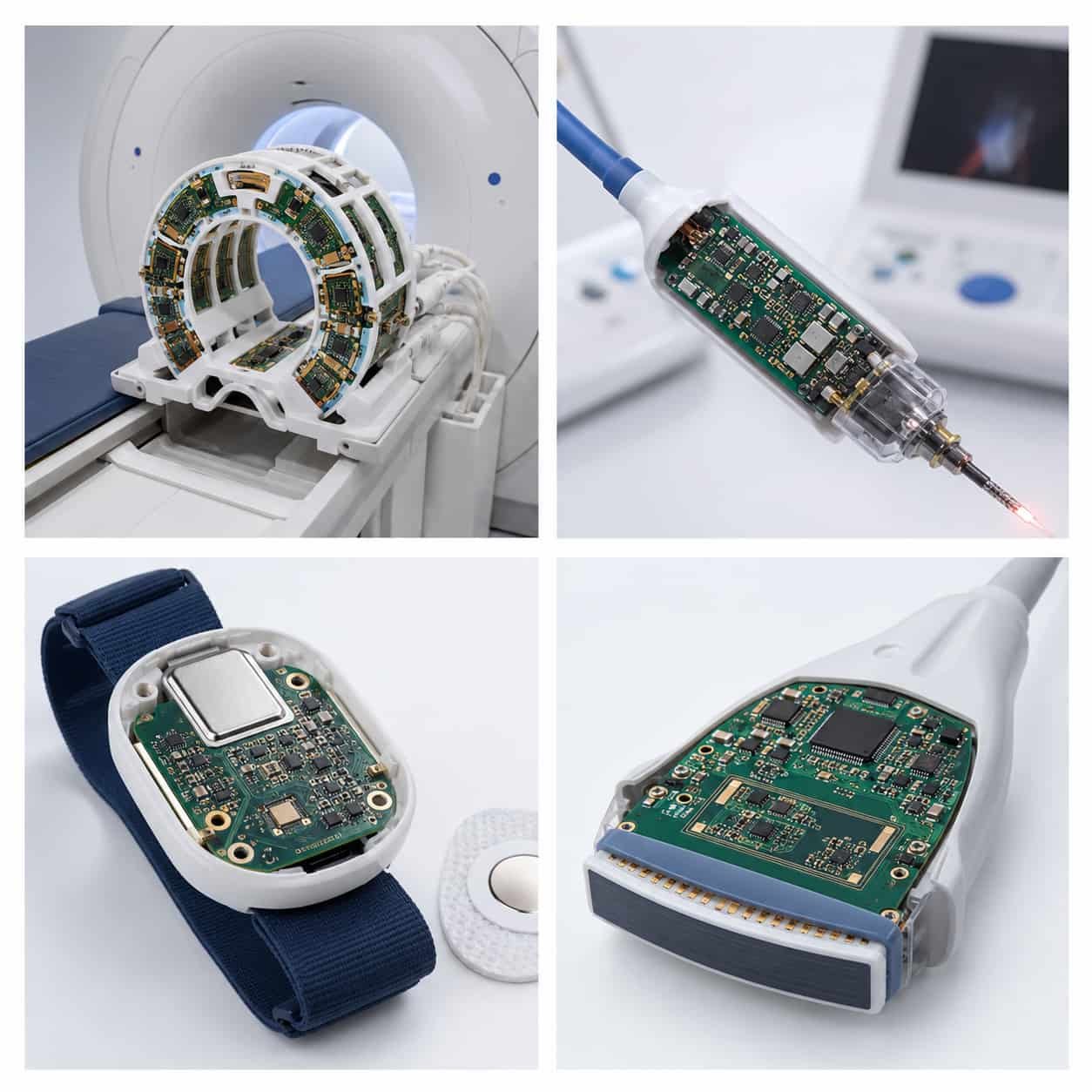
Quick Summary
Key point: Medical high frequency PCB requirements vary significantly by application. MRI RF coils require low-loss materials (Rogers RO4350B or RO3003) and very tight controlled impedance. Microwave ablation therapy operates at 2.45 GHz — Rogers RO4350B is typically adequate. Wireless patient monitoring uses standard ISM bands (2.4 GHz, 5.8 GHz, 915 MHz) where Rogers RO4350B or F4B materials are commonly used. All implantable or body-contact PCB require biocompatible materials and surface finishes. IPC Class 3 is the standard quality specification for medical-grade PCB requiring high reliability.
Medical RF and Microwave Applications Overview
MRI RF Coil PCB
Magnetic Resonance Imaging (MRI) systems use RF coils to transmit and receive the radio frequency signals that produce images. The RF frequency used depends on the static magnetic field strength:
- 5 Tesla MRI: RF frequency 63.87 MHz (proton Larmor frequency at 1.5T)
- 3 Tesla MRI: RF frequency 127.74 MHz
- 7 Tesla MRI: RF frequency 297.2 MHz
- Ultra-high field (7T+): RF coil PCB increasingly important for signal quality
MRI RF coil PCB requires very low dielectric loss (Df) because any loss in the transmit coil heats the patient through RF absorption, and any loss in the receive coil degrades signal-to-noise ratio (SNR). Rogers RO4350B is commonly used for receive coils where low Df and dimensional stability are the priority. Rogers RO3003 is specified for applications requiring even lower loss or better Dk stability.
- Material: Rogers RO4350B (standard), Rogers RO3003 (higher performance)
- Controlled impedance: 50Ω transmission lines, tight tolerance ±5–8%
- Surface finish: ENIG or ENEPIG — biocompatible gold surface
- Quality: IPC Class 3 for patient-contact applications
- Key requirement: dimensional stability over the MRI room temperature range and over scanner operating cycles
Microwave Ablation Therapy PCB
Microwave ablation (MWA) uses focused microwave energy to heat and destroy tumor tissue. The operating frequency is typically 2.45 GHz (ISM band) or 915 MHz, delivered through a percutaneous probe or catheter. The PCB at the generator end of the system controls microwave power delivery — it carries high-power 2.45 GHz signals from the magnetron or solid-state amplifier to the antenna feed.
- Frequency: 2.45 GHz (standard) or 915 MHz
- Power level: up to 100 W at 2.45 GHz — PCB must handle high RF power without degradation
- Material: Rogers RO4350B 0.508 mm or 0.762 mm — adequate Df at 2.45 GHz, handles RF power well
- Trace width: wide microstrip lines to handle RF current — confirmed power handling in DFM review
- Controlled impedance: 50Ω feed lines, ±10%
- Connector: SMA or N-type for high-power coaxial connection
- Surface finish: ENIG — required for reliability at high RF power
- Quality: IPC Class 3 — medical device reliability
Power handling: High-power RF PCB requires careful attention to copper weight and trace width. At 100W into 50Ω, the RMS current in the feed line is approximately 1.4A. Trace width must be adequate for this current without excessive resistive heating. Our DFM review confirms power handling for microwave ablation orders before production.
Wireless Patient Monitoring PCB
Wireless patient monitoring systems — vital sign monitors, telemetry systems, implantable device communication — use standard ISM band frequencies for the RF link between sensor and base station.
- 915 MHz (US ISM band): low-power implantable device communication, body area networks
- 4 GHz (IEEE 802.15.4, Bluetooth, WiFi): wearable patient monitors, bedside telemetry
- 8 GHz: higher-bandwidth wireless monitoring, hospital WiFi infrastructure
- MICS band (402–405 MHz): Medical Implant Communication Service — implantable cardiac devices
At these frequencies, Rogers RO4350B is the standard material for the RF front-end PCB in the monitoring device. For cost-sensitive wearable applications, F4B PTFE materials are also used where Rogers certification documentation is not required.
- Material: Rogers RO4350B (standard), F4BM220 or F4BM255 (cost-sensitive commercial)
- Antenna: patch antenna or dipole integrated on PCB — impedance matched to 50Ω
- Controlled impedance: 50Ω coplanar waveguide or microstrip feed
- Surface finish: ENIG
- Quality: IPC Class 2 for commercial wearables, IPC Class 3 for implantable communication PCB
See: Antenna PCB for Wireless Devices
Ultrasound Imaging PCB
Ultrasound imaging systems operate at frequencies from 1 MHz to 20 MHz for clinical imaging, with some specialized systems reaching 50 MHz or above. While these frequencies are below the typical RF/microwave range, the PCB in high-performance ultrasound systems requires controlled impedance and low-loss materials for the analog signal processing chain.
- Clinical imaging: 2–15 MHz — signal processing PCB
- High-frequency ultrasound: 20–50 MHz — specialized transducer electronics
- IVUS (intravascular ultrasound): 30–60 MHz — catheter-mounted imaging PCB
- Material: Rogers RO4350B for ultrasound analog front-end PCB at higher frequencies
- Key requirement: low noise analog signal path from transducer to ADC — controlled impedance for signal integrity
- IPC Class 3 for implantable or body-contact ultrasound transducer PCB
Medical Device RF PCB Material Selection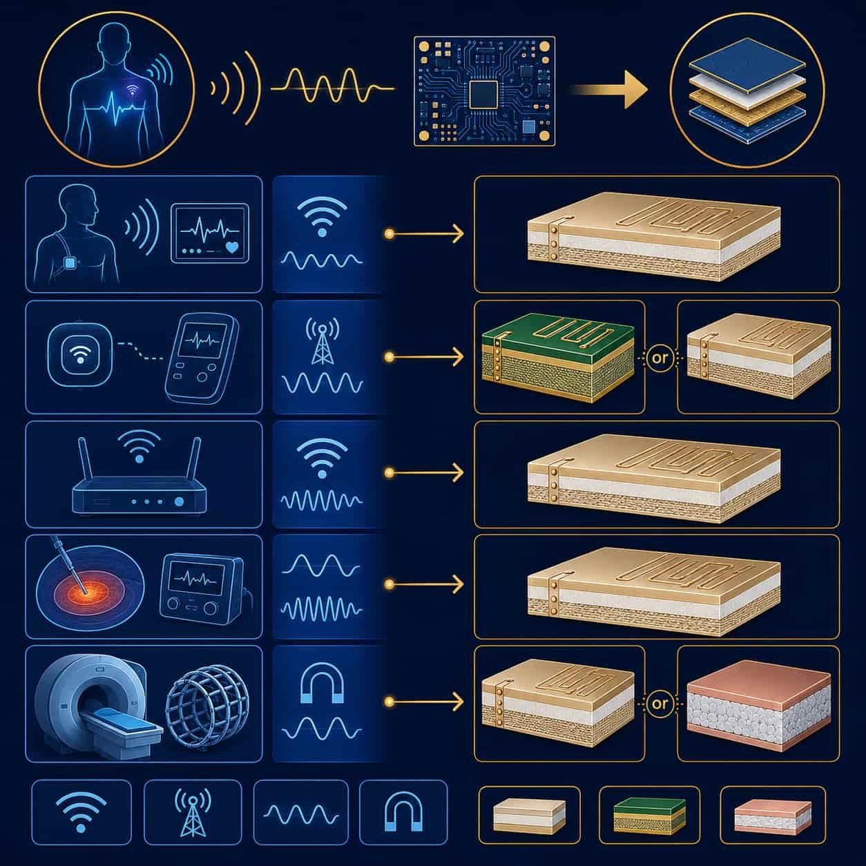
Rogers RO4350B for Most Medical RF Applications
Rogers RO4350B (Dk 3.48, Df 0.0037) is the most widely used material for medical device RF PCB. Its combination of adequate RF performance, FR4-compatible manufacturing, and well-established material certification history makes it the practical choice for MRI coils, microwave ablation generators, and wireless monitoring devices operating below 10 GHz.
- MRI RF coils at 64–300 MHz: RO4350B — very low Df at these frequencies, tight dimensional stability
- Microwave ablation at 2.45 GHz: RO4350B — adequate Df, good power handling
- Wireless monitoring at 2.4–5.8 GHz: RO4350B — adequate performance, well-certified material
- Ultrasound front-end at 1–50 MHz: RO4350B or high-Tg FR4 depending on frequency
Rogers RO3003 for Higher Performance Medical RF
For medical RF applications requiring lower Df or more stable Dk over temperature — such as high-field MRI coils at 300 MHz or specialized imaging applications at higher frequencies — Rogers RO3003 (Dk 3.0, Df 0.0010) provides better performance at higher cost and with PTFE manufacturing requirements.
- High-field MRI coils (7T, 297 MHz): RO3003 — lower Df for better SNR in high-field receive coils
- Millimeter-wave medical imaging (W-band): Rogers RT5880 — emerging applications in skin imaging and security scanning
F4B for Cost-Sensitive Commercial Medical Devices
Commercial wearable medical devices — fitness monitors, consumer health tracking — where Rogers-certified documentation is not required can use F4B PTFE materials for the RF front-end at lower cost than Rogers.
- Consumer wearable at 2.4 GHz: F4BM220 or F4BM255 — adequate performance, lower cost
- Not suitable for: implantable devices, patient-contact RF devices requiring certified material documentation
Quality Standards for Medical High Frequency PCB
IPC Class 3: Required for High-Reliability Medical PCB
IPC Class 3 is the quality workmanship standard for medical PCB requiring high reliability — implantable devices, life-critical monitoring, surgical instruments. IPC Class 3 requirements versus Class 2:
- PTH copper plating: 25 µm average with 20 µm minimum at any point (Class 2: 20 µm average only)
- Annular ring: no breakout on any layer (Class 2 permits internal layer breakout)
- Void limit: maximum 5% void per hole (Class 2: 10%)
- Electrical test: 100% of every board (Class 2: sampling permitted)
- Microsection analysis: periodic FAI to verify copper plating and laminate integrity
- Record retention: typically 10–30 years for medical device programs
Surface Finish for Medical PCB
- ENIG (standard): nickel 120–300 µin, gold 1–5 µin — most common for medical RF PCB
- ENEPIG: for wire bonding and highest reliability applications — eliminates black pad risk
- Immersion Silver: not recommended for implantable applications — silver migration risk in biologic environments
- OSP: not recommended for medical PCB — limited shelf life and potential biocompatibility concerns
- Hard gold: for edge connectors and contact surfaces on implantable devices
Biocompatibility Considerations
For PCB that will be in contact with patients — implantable devices, catheter-mounted PCB, skin-contact wearables — biocompatibility of the PCB materials and surface finishes must be considered. PCB laminate materials themselves (Rogers, PTFE) are generally considered biocompatible. The surface finish is the critical interface.
- ENIG gold surface: biocompatible — gold is widely accepted for patient-contact medical devices
- FR4 laminate base: epoxy-glass, generally considered biocompatible for non-implantable applications
- Rogers RO4350B: hydrocarbon ceramic — biocompatibility data available from Rogers Corporation
- Solder mask: standard LPI solder mask is not rated for implantable use — specialty biocompatible coatings required for fully implantable PCB
Important: PCB biocompatibility for implantable medical devices is a regulatory matter governed by ISO 10993 (Biological Evaluation of Medical Devices). Riching PCB provides PCB manufacturing — the medical device OEM is responsible for biocompatibility evaluation and regulatory approval of the complete device including PCB. We provide material certificates and lot documentation to support the OEM’s regulatory process.
Manufacturing Requirements for Medical High Frequency PCB
Controlled Impedance
- Standard tolerance: ±10% for most medical RF PCB
- Tight tolerance: ±8% or better for MRI coil and precision imaging PCB
- Verification: TDR measurement on every production lot — records retained for medical device programs
- Calculation: confirmed production Dk from Rogers material certificate — not nominal values
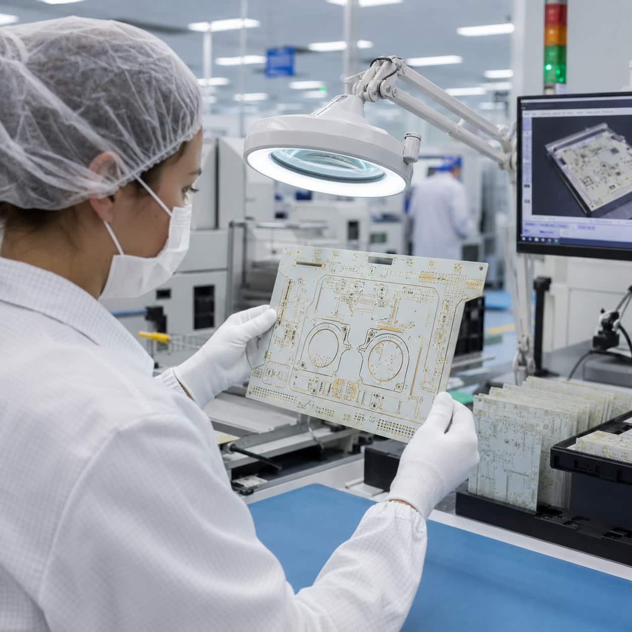
Cleanliness and Handling
- Ionic contamination: Rogers and PTFE PCB for medical applications require controlled ionic cleanliness — specified per IPC-7711/7721 or MIL-PRF-31032 depending on program requirements
- ESD control: standard ESD-protected handling for all medical RF PCB
- Packaging: individual packaging in static-shielded bags for medical device PCB
Documentation and Traceability
- Rogers material certificates: lot number and confirmed Dk/Df values — available for all Rogers production
- Certificate of Conformance: available for medical device programs
- First Article Inspection: microsection analysis report available for medical IPC Class 3 orders
- Record retention: specify required retention period (10, 20, or 30 years) at time of order
For full manufacturing capability details, see China High Frequency PCB Manufacturer: Rogers, PTFE, Taconic Direct Factory. For quotation files, see What Files Are Needed for a High Frequency PCB Quotation?.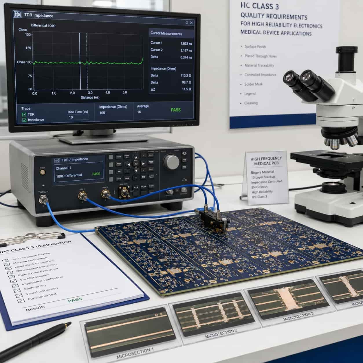
What to Specify for Medical High Frequency PCB
- Application type: MRI coil, microwave ablation, wireless monitoring, ultrasound — affects material and quality requirements
- Operating frequency and power level: determines material selection and trace width for power handling
- Rogers material grade and substrate thickness
- Complete stackup with layer sequence, material, copper weight
- Controlled impedance: target, tolerance, layer, structure
- IPC Class: 2 or 3 — specify Class 3 for life-critical or implantable applications
- Surface finish: ENIG standard; specify ENEPIG for wire bond or highest reliability
- Body contact or implantable: flag if PCB will be in patient contact
- Documentation requirements: Rogers material certificates, CoC, FAI microsection
- Record retention period
- Quantity: prototype or production volume
Conclusion
Medical device high frequency PCB spans a wide range of applications — from sub-100 MHz MRI RF coils to 2.45 GHz microwave ablation generators to 5.8 GHz wireless monitoring — each with specific material, impedance, quality, and documentation requirements. Rogers RO4350B covers the majority of medical RF applications below 10 GHz. Rogers RO3003 is used for higher-performance imaging coils and Ka-band medical applications. IPC Class 3 is the correct quality standard for life-critical and implantable medical device PCB.
As a direct high frequency PCB factory with IPC Class 3 capability, Rogers-certified material documentation, and TDR impedance verification on every production lot, we produce medical device RF PCB from prototype through production. Submit your requirements and our engineering team reviews material selection, power handling, and quality specification before production begins.