Automotive radar has become one of the fastest-growing applications for high frequency PCB. Modern vehicles use radar sensors for adaptive cruise control, automatic emergency braking, blind spot detection, lane change assist, and parking assistance. These systems operate at 24GHz for short-range sensing and increasingly at 77GHz and 79GHz for long-range, high-resolution detection required by advanced ADAS and autonomous driving applications.
The PCB inside an automotive radar sensor carries the RF front-end, antenna array, signal processing electronics, and power management in a compact, thermally demanding environment. The high frequency PCB must maintain consistent dielectric properties over a wide temperature range, survive automotive vibration and humidity, and support fine-pitch antenna structures at millimeter-wave frequencies. Standard FR4 materials cannot meet these requirements — specialized low-loss laminates are required.
This guide covers material selection, key electrical and thermal requirements, stackup design considerations, manufacturing specifications, and what to prepare before production for automotive radar PCB projects.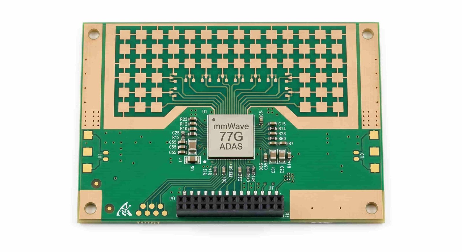
Quick Summary
Key point: Rogers RO3003 and RO3003G2 are the most widely used materials for 77GHz automotive radar PCB. Rogers RO4350B and Taconic RF-35 are used for 24GHz ADAS radar. Key requirements are stable Dk over temperature, low Df at millimeter-wave frequencies, controlled impedance ±10%, and thermal management for RF front-end chips. AEC-Q100 qualification requirements apply to components; PCB material thermal stability must be confirmed separately.
Automotive radar PCB design is more demanding than standard RF PCB because of the combination of high operating frequency, wide temperature range, long product lifetime, and high reliability requirements. Material selection, antenna trace geometry, via structure, thermal design, and surface finish must all be reviewed together during stackup planning.
Automotive Radar Frequencies and PCB Requirements
Automotive radar systems operate in two main frequency bands, each with different PCB material and manufacturing requirements:
24GHz Short-Range Radar
24GHz radar is used for parking sensors, blind spot monitoring, and short-range cross-traffic detection. At 24GHz, the PCB requirements are less stringent than at 77GHz, and a wider range of materials can be used. Rogers RO4350B, Taconic RF-35, and similar hydrocarbon or PTFE materials with Df below 0.004 are adequate for most 24GHz designs.
- Operating frequency: 24.0–24.25 GHz (ISM band) and 24.0–24.5 GHz
- Antenna wavelength at 24GHz: approximately 12.5 mm in free space
- PCB Dk and Df requirements: moderate — RO4350B, Taconic RF-35, F4B series suitable
- Typical application: parking sensors, blind spot detection, rear cross-traffic alert
77GHz and 79GHz Long-Range Radar
77GHz radar is the dominant frequency for long-range ADAS applications including adaptive cruise control, automatic emergency braking, and autonomous driving sensor fusion. At 77GHz, the wavelength is approximately 3.9 mm in free space and much shorter on the PCB. Trace width and spacing for antenna elements are in the range of 1–2 mm, requiring tight manufacturing tolerances and very low dielectric loss.
- Operating frequency: 76–77 GHz (long range) and 77–81 GHz (short/medium range)
- Antenna wavelength at 77GHz on RO3003: approximately 2.2 mm
- PCB Dk and Df requirements: stringent — Rogers RO3003, RO3003G2, RT5880 required
- Typical application: adaptive cruise control, automatic emergency braking, pedestrian detection, highway autopilot
Key point: At 77GHz, a Dk variation of just ±0.05 shifts the antenna resonant frequency by approximately 1%, which is enough to affect beam pattern and detection range. Material Dk consistency — both lot-to-lot and over temperature — is a critical selection criterion.
Material Selection for Automotive Radar PCB
Material selection is the most critical design decision for automotive radar PCB. The material must provide stable Dk at millimeter-wave frequencies, low Df to minimize signal loss in antenna feed lines, low CTE to minimize dimensional change over temperature, and adequate thermal conductivity for heat dissipation from RF front-end chips.
| Material | Dk | Df | CTE (ppm/°C) | Best For |
|---|---|---|---|---|
| Rogers RO3003 | 3.0 | 0.0010 | 17 | 77GHz radar, low loss |
| Rogers RO3003G2 | 3.0 | 0.0010 | 17 | 77GHz, improved loss |
| Rogers RT5880 | 2.2 | 0.0009 | 31 | Ultra-low loss radar |
| Rogers RO4350B | 3.48 | 0.0037 | 32/46 | 24GHz, cost-sensitive |
| Taconic RF-35 | 3.5 | 0.0018 | 14 | 24GHz ADAS, low CTE |
| Taconic CER-10 | 10.0 | 0.0035 | — | High Dk antenna elements |
| F4BM220 | 2.20 | 0.0010 | — | Budget radar PCB |
Rogers RO3003 and RO3003G2
Rogers RO3003 is the most widely adopted material for 77GHz automotive radar PCB. It provides Dk of 3.0 ±0.04, Df of 0.0010 at 10 GHz, and low CTE of 17 ppm/°C in the x-y plane, which is close to copper and supports good dimensional stability over the automotive temperature range of -40°C to +125°C.
RO3003G2 is an improved version with better insertion loss at millimeter-wave frequencies, particularly above 60GHz. It is increasingly specified for new 77GHz and 79GHz radar designs requiring lower loss in longer antenna feed lines.
- Dk: 3.0 ±0.04 — tight tolerance for consistent antenna resonance
- Df: 0.0010 at 10 GHz — very low loss for 77GHz antenna feed lines
- CTE (x-y): 17 ppm/°C — good dimensional stability over temperature
- Operating temperature: -40°C to +150°C — suitable for under-hood automotive
- Available thicknesses: 0.127 mm, 0.254 mm, 0.508 mm, 0.762 mm, 1.524 mm
Rogers RT5880
Rogers RT5880 offers the lowest Dk (2.2) and Df (0.0009) of commonly used automotive radar materials, making it suitable for applications requiring the absolute minimum insertion loss. However, its higher CTE (31 ppm/°C in x-y plane) compared to RO3003 means more dimensional change over temperature, which must be accounted for in antenna design.
- Best suited for ultra-low loss antenna feed networks and long antenna arrays
- Higher CTE requires careful thermal expansion analysis in large antenna apertures
- PTFE base — requires special process for hole wall preparation before plating
Rogers RO4350B for 24GHz
Rogers RO4350B is a cost-effective choice for 24GHz radar PCB where the higher Df of 0.0037 is acceptable. Its hydrocarbon ceramic base is compatible with standard FR4 lamination processes, making it more economical for high volume 24GHz designs. It is not recommended for 77GHz applications where insertion loss is critical.
Taconic RF-35
Taconic RF-35 (Dk 3.5, Df 0.0018) is an alternative to Rogers for 24GHz ADAS radar PCB. It offers lower CTE than RO4350B and lower Df than standard hydrocarbon materials, making it suitable for mid-range ADAS applications where cost and performance must be balanced.
For detailed Rogers material properties and selection guidance, see Rogers PCB Material Selection Guide for RF and Microwave Applications. For Taconic material options, see Taconic PCB Materials for RF and Microwave Applications.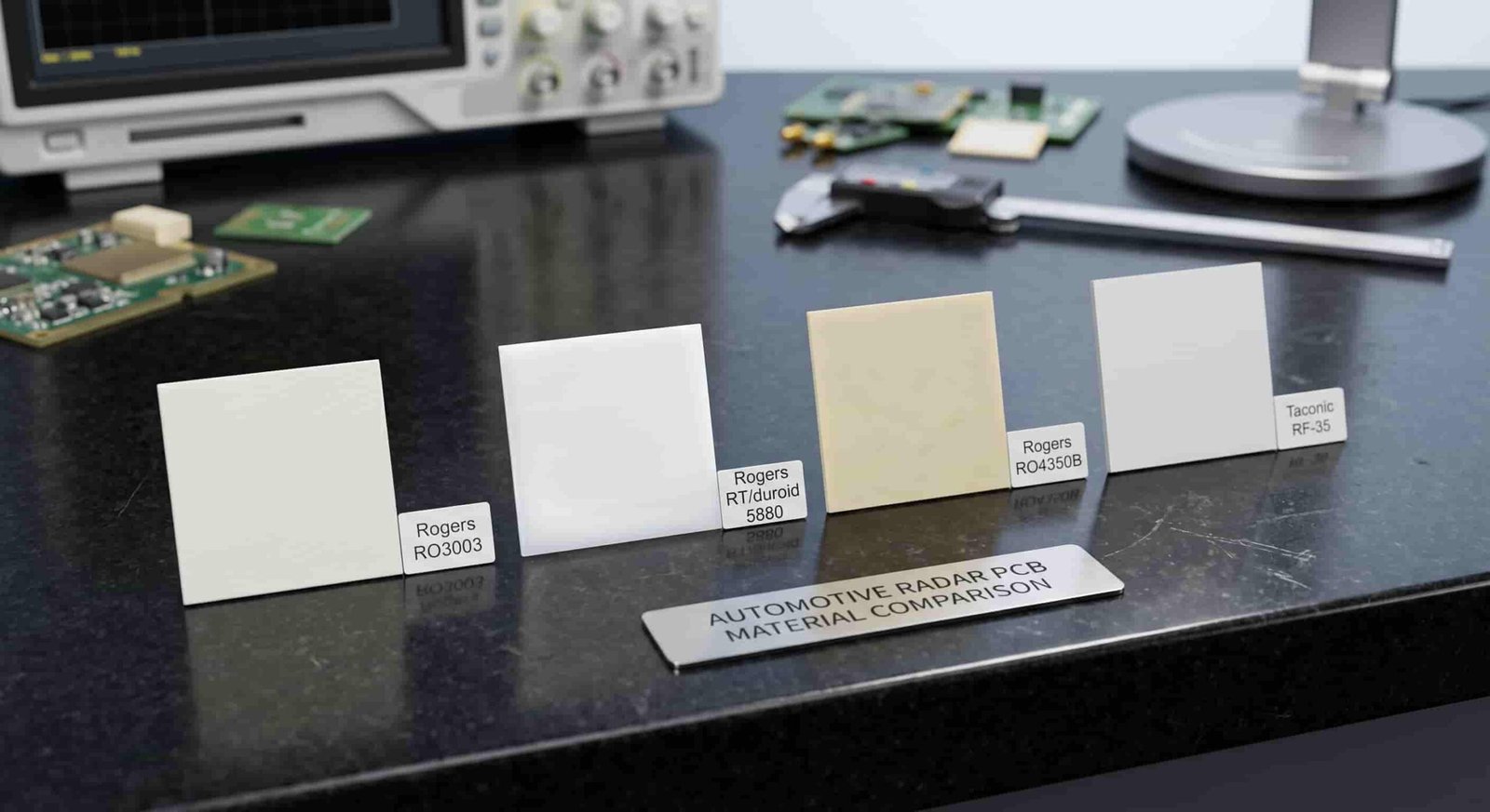
Antenna PCB Design Considerations for Automotive Radar
The antenna is the most sensitive part of the automotive radar PCB. Patch antenna arrays, series-fed arrays, and corporate-fed arrays are commonly used at 77GHz. The antenna element dimensions, feed line geometry, and ground plane structure are all directly affected by the PCB material properties and manufacturing tolerances.
Patch Antenna Dimensions at 77GHz
At 77GHz on Rogers RO3003 (Dk 3.0, thickness 0.254 mm), a typical half-wavelength patch antenna element is approximately 1.1–1.2 mm wide and 1.0–1.1 mm long. The feed line width for 50Ω microstrip on the same material is approximately 0.6–0.7 mm. These dimensions require minimum line width capability of 2.5–3 mil in production.
- Patch antenna element size: approximately 1.0–1.2 mm at 77GHz on RO3003 0.254 mm
- 50Ω microstrip feed line width: approximately 0.6–0.7 mm on RO3003 0.254 mm
- Antenna array spacing: approximately half-wavelength (~1.1 mm) for standard beam patterns
- Feed line phase matching: length tolerance must be tight for phased array designs
Effect of Dk Variation on Antenna Performance
Because antenna dimensions are calculated based on the material Dk, any variation in Dk shifts the resonant frequency and changes the radiation pattern. At 77GHz, a 1% Dk variation causes approximately 0.5% frequency shift — about 385 MHz. For a 500 MHz bandwidth radar system, this is significant.
- Use material with tight Dk tolerance: RO3003 specifies Dk 3.00 ±0.04
- Request material Dk certificate from manufacturer when lot consistency is critical
- Account for Dk temperature coefficient in antenna design for -40°C to +125°C range
Ground Plane and Via Structure
A continuous, unbroken ground plane directly below the antenna layer is critical for consistent radiation pattern and antenna efficiency. Splits, slots, or cutouts in the ground plane under the antenna area cause impedance discontinuities and pattern distortion.
- Avoid traces, vias, or cutouts in the ground plane under antenna elements
- Via fences around the feed network reduce lateral signal leakage
- Through-hole vias for ground transitions must not penetrate the antenna aperture area
For antenna PCB design and grounding considerations, see Antenna PCB for Wireless Devices and RF Front-End Modules.
Thermal Management in Automotive Radar PCB
Automotive radar sensors operate in demanding thermal environments. Under-hood applications may see ambient temperatures from -40°C to +105°C or higher. The RF front-end MMIC (Monolithic Microwave Integrated Circuit) generates significant heat that must be conducted away from the chip through the PCB to a heat spreader or housing.
Thermal Via Arrays
Thermal vias placed under RF chip packages (QFN, LGA, or flip-chip) conduct heat from the chip pad through the PCB to the opposite side or to internal copper planes. The density and diameter of thermal vias determine the effective thermal conductivity through the board.
- Thermal via diameter: typically 0.2–0.4 mm for RF chip packages
- Thermal via pitch: 0.6–1.0 mm for standard thermal via arrays
- Via fill: copper-filled or resin-filled vias improve planarity for chip attachment
- Copper pour on all available layers improves lateral heat spreading
Material Thermal Conductivity
Rogers RO3003 has a thermal conductivity of approximately 0.5 W/m·K, which is higher than standard FR4 (0.3 W/m·K) but lower than ceramic or metal-core substrates. For automotive radar chips with moderate power dissipation (typically 1–3W for a 77GHz front-end MMIC), the combination of thermal vias and copper spreading is usually sufficient.
- RO3003 thermal conductivity: ~0.5 W/m·K
- RT5880 thermal conductivity: ~0.2 W/m·K (lower — less suitable for high-power chips)
- Consider copper coin insert or metal-backed substrate for chips above 3W dissipation
Manufacturing Requirements for Automotive Radar PCB
Line Width and Spacing
At 77GHz, antenna trace dimensions are very fine. The minimum line width and spacing capability of the manufacturer must be confirmed before finalizing the design.
- Minimum outer layer line width: 2.5 mil (advanced capability) for 77GHz antenna traces
- Minimum outer layer line spacing: 3 mil (advanced capability)
- Etching tolerance for impedance traces: ±1 mil for traces below 10 mil width
- Trace width consistency across the antenna array is critical for beam pattern uniformity
Controlled Impedance
All RF feed lines in automotive radar PCB require controlled impedance. The impedance target is typically 50Ω for single-ended feed lines and 100Ω differential for balanced structures.
- Standard impedance tolerance: ±10% (≥ 50Ω)
- Advanced impedance tolerance: ±8%
- Impedance must be verified with test coupons after production
- Stackup must be confirmed with actual material Dk, not just nominal datasheet value
Drilling and Via Requirements
Automotive radar PCB typically uses through-hole vias for ground connections and component mounting. Via diameter and position tolerance affect ground continuity and component fit.
- Minimum drill diameter: 0.2 mm standard, 0.1 mm advanced
- Hole position tolerance: ±0.05 mm advanced
- Via fence spacing for 77GHz shielding: typically ≤ λ/20 at operating frequency
Surface Finish
Surface finish for automotive radar PCB affects antenna pad performance, solderability of RF chips, and long-term reliability in the automotive environment.
- ENIG (Electroless Nickel Immersion Gold): most common for 77GHz radar PCB — flat surface, stable RF pad performance
- ENEPIG: used where wire bonding or high-reliability pad requirements apply
- Immersion Silver: good RF surface, requires protection from tarnish in automotive environments
- OSP: generally not recommended for automotive radar pads due to limited shelf life and thermal exposure
For surface finish options and specifications, see Surface Finish Options for RF and Microwave PCB. For drilling capabilities, see Drilling Capabilities for High Frequency PCB.
Reliability Requirements for Automotive Radar PCB
Automotive electronics must meet reliability standards that are more demanding than commercial or industrial applications. The PCB material, surface finish, and manufacturing process must be selected to support the expected product lifetime.
- Operating temperature range: typically -40°C to +105°C for body-mounted radar, -40°C to +125°C for under-hood
- Thermal cycling: IEC 60068-2-14 or JEDEC JESD22-A104 thermal shock testing
- Humidity resistance: IEC 60068-2-78 damp heat testing
- Vibration: ISO 16750-3 mechanical load testing
- Material Tg: Rogers RO3003 Tg > 500°C (PTFE base) — excellent for automotive temperature range
- Lead-free solder compatibility: ENIG and ENEPIG surface finishes support lead-free reflow at 260°C peak
Note: AEC-Q100 qualification applies to electronic components and ICs, not to PCB substrates directly. However, the PCB material must be selected to support the AEC-Q100 test conditions applied to the assembled module. Rogers RO3003 and RT5880 are widely used in AEC-Q100 qualified automotive radar modules.
Typical Stackup Examples for Automotive Radar PCB
2-Layer 77GHz Radar PCB (Simplest)
A 2-layer radar PCB places the antenna array and RF front-end on the top layer with a full ground plane on the bottom. This is the simplest and lowest-cost configuration, suitable for single-channel short-range radar sensors.
- Layer 1 (top): antenna array, RF feed lines, chip pads
- Layer 2 (bottom): continuous ground plane
- Material: Rogers RO3003 0.254 mm
- Surface finish: ENIG
4-Layer 77GHz Radar PCB (Most Common)
A 4-layer stackup separates the RF antenna layer from the digital signal processing layer and provides dedicated power and ground planes. This is the most common configuration for modern 77GHz ADAS radar sensors.
- Layer 1 (top): antenna array and RF front-end
- Layer 2: ground reference plane
- Layer 3: power and digital signal routing
- Layer 4 (bottom): ground plane and heat spreading
- RF layers: Rogers RO3003 or hybrid with FR4 on inner layers
6-Layer Phased Array Radar PCB
Phased array radar systems with multiple transmit and receive channels require more layers for RF routing, beam forming network, digital control, and power management. 6 to 8 layers are typical for automotive phased array radar modules.
For multilayer stackup design, see Multilayer High Frequency PCB: Layer Count, Stackup and Manufacturing Limits. For hybrid stackup options, see FR4 + Rogers Hybrid PCB Stackup: When Should You Use It?.
Information Needed for Automotive Radar PCB Quotation
To review feasibility and provide an accurate quotation for automotive radar PCB, the following information should be included:
- Gerber files (all layers)
- Complete PCB stackup with layer sequence, material, and dielectric thickness
- Operating frequency — 24GHz, 77GHz, or 79GHz
- Material preference — Rogers RO3003, RT5880, RO4350B, Taconic, or other
- Layer count and board thickness
- Controlled impedance requirements — 50Ω microstrip, 100Ω differential, or other
- Via structure — through-hole, thermal vias, blind or buried
- Surface finish requirement
- Thermal requirements — chip power dissipation, thermal via density
- Reliability requirements — temperature range, humidity, vibration standard
- Quantity — prototype or batch production
- Any automotive qualification requirements
For a complete file and information checklist, see What Files Are Needed for a High Frequency PCB Quotation?.
Conclusion
Automotive radar PCB for 24GHz ADAS and 77GHz long-range radar applications requires careful material selection, tight manufacturing tolerances, and thermal management design. Rogers RO3003 and RO3003G2 are the leading materials for 77GHz radar, offering stable Dk, very low Df, and low CTE across the automotive temperature range. Rogers RO4350B and Taconic RF-35 cover most 24GHz applications at lower cost.
Manufacturing requirements including minimum line width of 2.5 mil, controlled impedance ±10%, ENIG surface finish, and thermal via arrays must be confirmed with the high frequency PCB manufacturer before production. Early stackup review and material confirmation reduce design iteration and support reliable automotive module production.