Unmanned systems — unmanned aerial vehicles (UAV), unmanned ground vehicles (UGV), unmanned surface vessels (USV), and autonomous platforms of all types — are among the fastest-growing application areas for defense and commercial high frequency PCB. A modern military UAV may carry synthetic aperture radar (SAR), a signals intelligence (SIGINT) receiver, a datalink system for command and sensor data, and a self-protection EW pod — all simultaneously, all in a volume and weight budget far smaller than a manned aircraft.
The defining constraint for unmanned system electronics is SWaP-C: Size, Weight, Power, and Cost. Every gram of payload PCB displaces endurance, every cubic centimeter of volume competes with sensors and batteries, and every watt of power consumption reduces mission duration. These constraints drive high frequency PCB design toward the most compact, lightest, most power-efficient solution achievable — without compromising the RF performance that determines whether the payload can accomplish its mission.
This guide covers the high frequency PCB requirements for UAV and unmanned system payloads, Rogers material selection for different payload types, SWaP-C driven design constraints, miniaturization manufacturing requirements, environmental qualification, and what to prepare before production.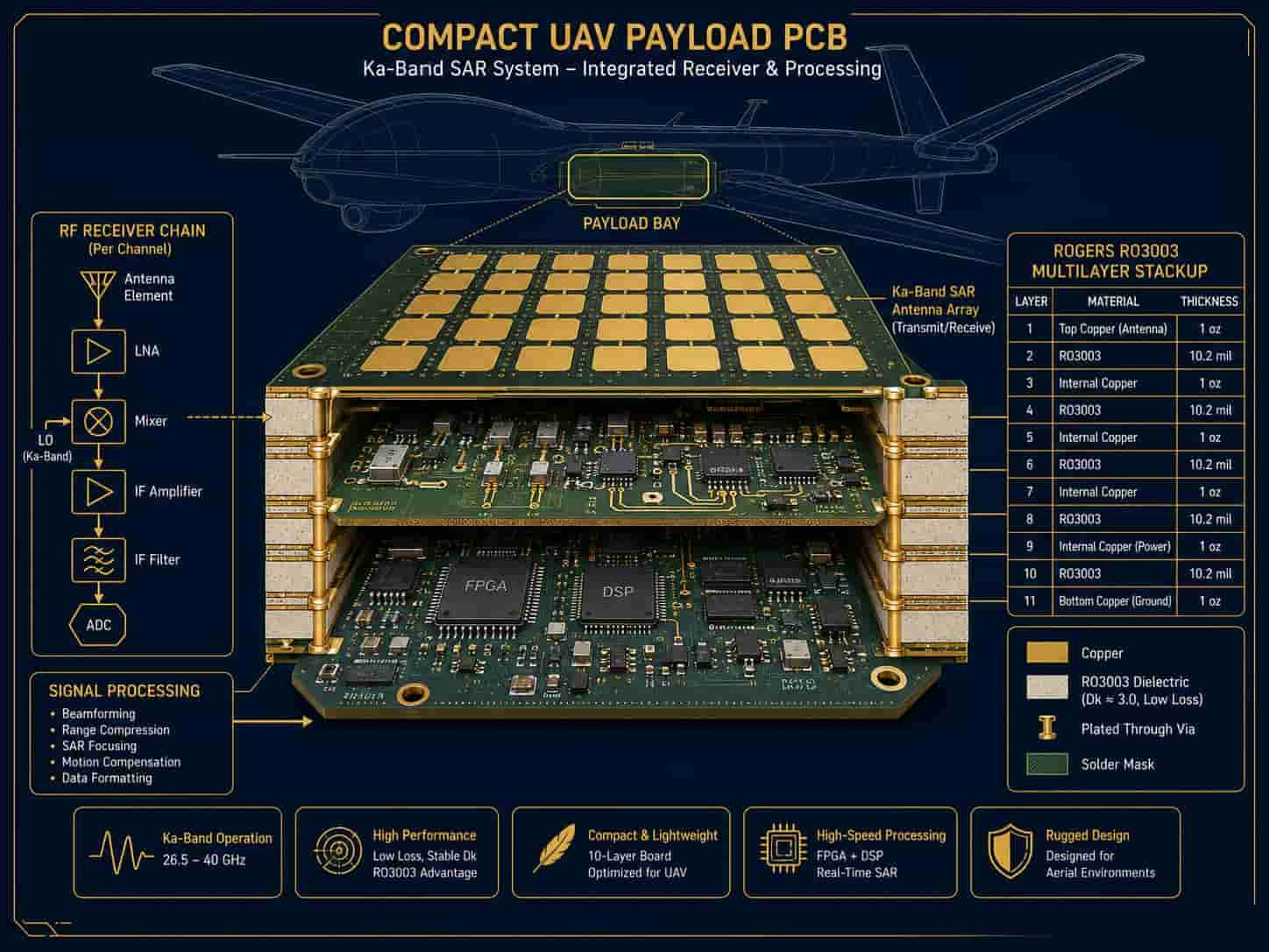
Quick Summary
Key point: UAV and unmanned system high frequency PCB uses Rogers RO4350B for L-band and S-band payloads, Rogers RO3003 for Ka-band SAR radar and datalink, and Rogers RT5880 for SIGINT and EW payloads covering 2–18 GHz. SWaP-C optimization drives board thickness below 1.0 mm, maximum component density, and hybrid FR4 + Rogers stackups to minimize weight. IPC Class 3 applies to military UAV. Commercial UAV uses IPC Class 2 or Class 3 depending on program requirements.
The key distinction between UAV PCB and other defense high frequency PCB is that SWaP-C optimization is not optional — it is the primary design constraint that shapes every decision from material selection to layer count to component choice. A board that is 20% lighter, 15% smaller, or 10% more power-efficient than the previous design is a meaningful improvement that translates directly into mission capability. This makes unmanned system PCB design one of the most challenging optimization problems in the field.
Unmanned System Types and High Frequency PCB Payload Requirements
Unmanned systems carry a wide variety of high frequency payloads depending on the mission. Understanding the specific payload type and platform class is the starting point for PCB specification.
Synthetic Aperture Radar (SAR) Payload
SAR radar is one of the highest-value payloads for military UAV, providing all-weather, day-night ground imaging with resolution from meters down to centimeters for GMTI (Ground Moving Target Indicator) and change detection missions. SAR radar is also increasingly used on commercial UAV for topographic mapping and infrastructure inspection.
- X-band SAR (8–12 GHz): Rogers RO4003C or RO3003 — most common for UAV SAR
- Ka-band SAR (26.5–40 GHz): Rogers RO3003 — higher resolution imaging at shorter range
- Compact antenna: SAR antenna must be conformal to airframe or stowed for deployment — thin substrate required
- Weight: SAR radar PCB weight budget is typically 200–500 g for a small UAV payload
- Dual-band SAR: some payloads combine X-band and Ka-band — hybrid stackup or separate boards
SIGINT and ELINT Receivers
Signals intelligence (SIGINT) and electronic intelligence (ELINT) payloads intercept and record radar and communication emissions. They require the widest frequency coverage and lowest insertion loss of any UAV payload to maximize detection range and signal fidelity.
- Frequency coverage: 2–18 GHz standard, up to 40 GHz for advanced ELINT
- Rogers RT5880 — minimum loss across full SIGINT band
- Multiple receive channels: simultaneous coverage of multiple frequency bands
- High dynamic range: PCB must support ADC with very high spurious-free dynamic range
- Low power: SIGINT receiver is passive — power budget dominated by signal processing, not RF
Command and Sensor Datalink
UAV datalink provides the communication link between the UAV and its ground control station for command uplink and sensor data downlink. High data rate downlink for SAR imagery and video requires wideband communication systems at Ku-band or Ka-band.
- C-band command link (4–6 GHz): Rogers RO4350B — standard for military command uplink
- Ku-band data downlink (10.7–14.5 GHz): Rogers RO4003C or RO3003 — high data rate SAR imagery
- Ka-band SATCOM (17–31 GHz): Rogers RO3003 — satellite relay for beyond line-of-sight operation
- Antenna: small directional or phased array antenna — light weight critical
- Link margin: every dB of PCB insertion loss reduces maximum range or data rate
UAV EW Payload — Self-Protection and Offensive
Military UAV carry self-protection EW for survivability in contested airspace and may also carry offensive EW payloads for suppression or disruption of enemy radar and communication. EW payload PCB requirements closely mirror those of airborne EW systems but with even tighter SWaP constraints.
- Self-protection RWR (2–18 GHz): Rogers RT5880 — minimum loss for maximum warning range
- Active jamming ECM: Rogers RT5880 or RO3003 — power handling for GaN jammer
- DRFM (Digital Radio Frequency Memory): wideband receive and transmit — Rogers RT5880
- Weight: EW pod PCB weight budget is typically 100–300 g for a small UAV pod
UGV Radar and Communication
Unmanned ground vehicles carry radar for obstacle avoidance, terrain navigation, and target detection. The PCB requirements for UGV radar are similar to automotive radar at 77GHz but with defense-grade reliability and environmental qualification.
- 77GHz obstacle avoidance radar: Rogers RO3003 — same as automotive radar PCB requirements
- UGV communication datalink: S-band or X-band — Rogers RO4350B or RO4003C
- Environmental: UGV PCB must survive mud, water splash, vibration from rough terrain — conformal coating essential
- Power: UGV battery budget constrains RF transmitter power — efficiency is critical
SWaP-C Optimization for Unmanned System High Frequency PCB
SWaP-C — Size, Weight, Power, and Cost — is the overriding design constraint for unmanned system electronics. Every decision in the PCB design process must be evaluated against its SWaP-C impact. This section covers the primary SWaP-C levers available in high frequency PCB design.
Size Reduction
Reducing PCB footprint reduces the volume allocated to the payload electronics, potentially allowing a larger antenna, more sensors, or a smaller airframe with the same payload capability.
- Higher layer count: routing all circuits in fewer layers on smaller boards — 8–16 layers common for compact UAV payload PCB
- HDI blind vias: enables smaller via pitch and pad sizes for higher component density
- Component miniaturization: 0201 or 01005 passives, BGA RF chips — highest density assembly
- Integrated modules: use integrated transceiver chips that combine multiple RF functions
- Circular or conformal boards: match board shape to airframe cross-section
Weight Reduction
Weight is typically the most critical SWaP-C parameter for UAV payloads. Every gram of PCB weight displaces either payload capability or fuel for endurance.
- Thin substrates: Rogers RO3003 available in 0.127 mm — thinnest standard substrate for Ka-band SAR
- Total board thickness: minimize total stackup thickness — thin boards are lighter boards
- Copper weight: use minimum copper weight consistent with current carrying requirement — thinner copper means lighter board
- Hybrid stackup: Rogers on RF layers, thin FR4 on digital layers — FR4 is lighter than Rogers for the same thickness
- Board material selection: Rogers RO4350B density 1.86 g/cm³, RO3003 density 2.1 g/cm³ — density difference affects total board weight for large panels
- Component selection: choose lightest package for each function — QFN and chip-scale packages over larger leaded packages
Power Reduction
Power consumption affects both battery life on battery-powered UAV and thermal management requirements on larger platforms. Lower power consumption means longer missions or reduced cooling system complexity.
- GaN vs GaAs: GaN provides higher efficiency for RF power amplifiers — less heat for same output power
- Low-power LNA: minimize receiver noise figure with lowest-power LNA that meets sensitivity requirement
- Power management: duty cycle the radar when not scanning — significant average power reduction
- PCB insertion loss: lower Df Rogers material means less power wasted heating the substrate
- Digital processing: use FPGAs or application-specific processors optimized for power efficiency
Cost Management
For high-volume commercial UAV and attritable military UAV programs, PCB cost is a significant factor. Cost management in high frequency UAV PCB involves material selection, manufacturing process, and quantity planning.
- Rogers RO4350B vs RO3003: RO4350B is lower cost — use at frequencies where its Df is acceptable
- Hybrid FR4 + Rogers: significant cost saving vs full Rogers construction for multi-layer boards
- ZY alternative materials: for commercial UAV where Rogers-certified documentation is not required
- Standard panel sizes: design to fit standard manufacturing panels — minimizes material waste
- Volume: high-volume commercial UAV programs reduce per-unit PCB cost significantly
Design guidance: For military UAV where performance and reliability are paramount, SWaP-C optimization should follow the priority: Size (to fit the platform) → Weight (to maximize endurance) → Power (to maximize mission duration) → Cost (to enable procurement). For commercial UAV where cost drives adoption, the priority often reverses: Cost → Size → Power → Weight.
Miniaturization Manufacturing Requirements for UAV PCB
The SWaP-C constraints of unmanned system payloads push UAV high frequency PCB toward the limits of manufacturing capability. Fine line widths, thin substrates, HDI blind vias, and high component density all require a manufacturer with demonstrated capability in compact high frequency PCB production.
Minimum Line Width for UAV Payloads
- Ka-band SAR antenna feed (35 GHz on RO3003 0.127 mm): trace width approximately 0.25–0.3 mm (10–12 mil)
- Ka-band 50Ω microstrip (RO3003 0.254 mm): trace width approximately 0.6 mm (24 mil)
- X-band SAR feed (10 GHz on RO4003C 0.508 mm): trace width approximately 1.2 mm (47 mil)
- Manufacturing minimum: 2.5 mil line width for Ka-band UAV payload PCB — requires advanced capability
- Tolerance: ±1 mil for traces below 10 mil — tighter than standard ±20% for wider traces
Thin Substrate Processing
Very thin Rogers substrates (0.127 mm and 0.254 mm) require specialized handling during all manufacturing steps to prevent warpage, cracking, or dimensional distortion that would affect Ka-band antenna element dimensions.
- Panel handling: thin panels require special carriers and fixtures during processing
- Drilling: CNC drill parameters optimized for thin PTFE — standard parameters cause warpage
- Lamination: thin layers require precise lamination pressure and temperature control
- Warpage: thin PTFE boards may bow during processing — fixturing required
- Dimensional accuracy: Ka-band antenna element tolerance ±0.05 mm requires tight panel dimensional control
HDI for Dense UAV Payload PCB
High density interconnect (HDI) with laser blind vias enables the component density needed for compact UAV payload PCB. Routing 8–12 layers of RF, digital, and power circuits within a small board footprint requires blind via structures.
- 1-stage HDI: most common for UAV payload PCB — adds one laser via layer
- 2-stage HDI: for highest density designs — limited by 2 press cycle maximum for PTFE materials
- Laser via diameter: 3–4 mil minimum — limited by PTFE dielectric thickness
- Via-in-pad: enables highest component density — required for BGA RF chip packages on compact UAV PCB
- Copper fill: laser blind vias should be copper-filled for planarity and reliability
For HDI capabilities, see Blind and Buried Via Capabilities in High Frequency PCB Manufacturing. For drilling capabilities, see Drilling Capabilities for High Frequency PCB.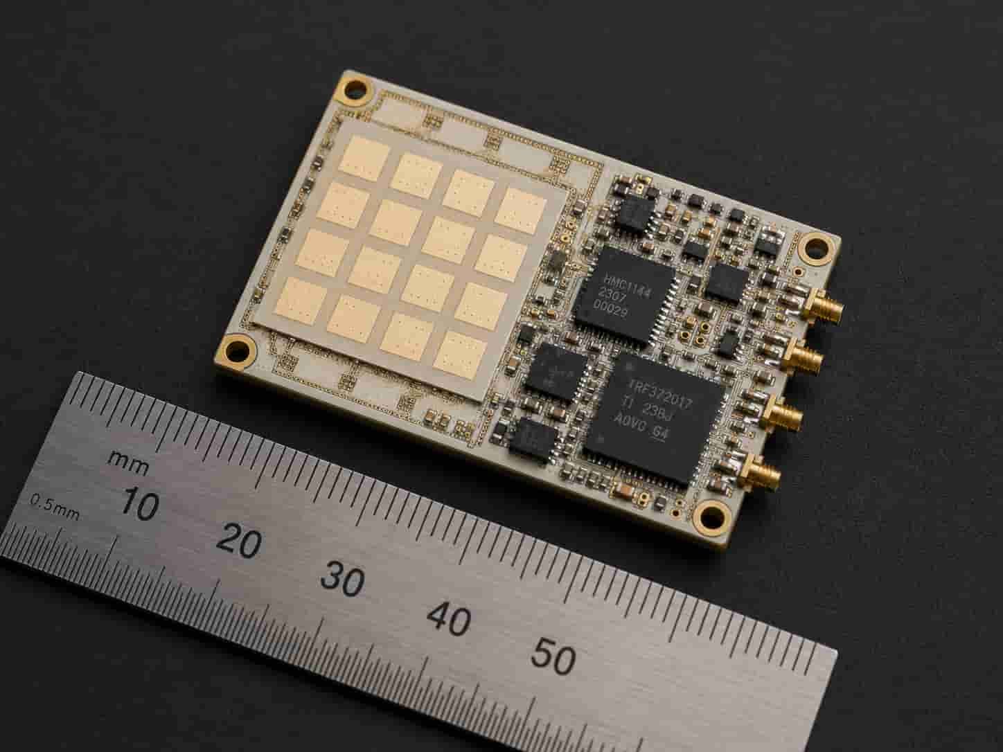
Environmental Requirements for UAV and Unmanned System PCB
UAV and unmanned system PCB faces environmental requirements that combine elements of airborne, ground vehicle, and sometimes naval requirements depending on the platform and operating environment.
Temperature Range
- Small tactical UAV: -40°C to +70°C operating, -55°C to +85°C storage
- High-altitude long-endurance (HALE) UAV: -65°C to +55°C operating — high altitude cold environments
- UGV: -40°C to +85°C operating — ground vehicle engine bay temperatures
- Rogers RO3003 PTFE base: no Tg concern across any UAV operating temperature range
- Rogers RO4350B Tg > 280°C: adequate for all UAV operating temperatures
Vibration
- Fixed-wing UAV: propeller or turbine vibration — typically 20–200 Hz
- Rotary-wing UAV / drone: rotor vibration — typically 10–100 Hz fundamental frequency
- UGV: rough terrain vibration — broadband 5–500 Hz
- MIL-STD-810 Method 514.8: applicable to military UAV PCB
- PCB natural frequency: should be above primary vibration excitation frequency
- Conformal coating: helps retain solder joints under sustained vibration
Humidity and Condensation
- Outdoor operation at all altitudes: UAV PCB experiences condensation during altitude transitions
- Conformal coating: standard for military UAV — protects against humidity and condensation
- Tropicalized UAV: additional humidity and fungal protection required for tropical operations
- Rogers PTFE materials: hydrophobic — low moisture absorption advantage
Altitude and Reduced Pressure
- HALE UAV operation above 60,000 ft (18,000 m): very low air pressure — corona discharge spacing must be increased
- Reduced air pressure affects RF component cooling — thermal management must account for reduced convection
- Sealed enclosures: some UAV payload electronics are hermetically sealed for altitude operation
Military vs Commercial UAV PCB: Different Quality and Documentation Requirements
The quality and documentation requirements for military UAV PCB differ significantly from commercial UAV PCB, affecting material specification, manufacturing standards, and traceability documentation.
Military UAV PCB Requirements
- IPC Class 3 workmanship: standard for all military UAV electronics
- Rogers-certified material: material certificates with Rogers Corporation lot numbers
- Full traceability: material certificates, process records, serialization
- MIL-STD-810 environmental qualification: temperature, vibration, humidity, altitude
- Controlled impedance verification: TDR measurement every production lot
- First article inspection: microsection, plating thickness, surface finish measurement
- MIL-PRF-31032: applicable to US military UAV PCB programs
Commercial UAV PCB Requirements
- IPC Class 2 or Class 3: depends on criticality and customer specification
- Material: Rogers, ZY, or other qualified high frequency laminate — Rogers-certified not always required
- Cost sensitivity: material substitution with customer approval may be acceptable
- Environmental: DO-160G environmental qualification for civil UAS (unmanned aircraft system)
- Airworthiness: civil UAS certification may require hardware development assurance per DO-254
- Volume: commercial UAV programs may be high volume — manufacturing cost optimization more important
Note: The FAA and other civil aviation authorities are developing certification frameworks for commercial UAS that operate beyond visual line of sight (BVLOS) or carry payloads in controlled airspace. As these frameworks mature, the documentation and quality requirements for commercial UAV electronics PCB are expected to increase toward military UAV standards, particularly for BVLOS and urban air mobility applications.
Information Needed for Unmanned System High Frequency PCB Quotation
To review feasibility and provide an accurate quotation for UAV and unmanned system high frequency PCB, the following information should be prepared:
- Gerber files (all layers) and NC drill files
- Complete PCB stackup with Rogers material grade, layer sequence, and copper weight
- Platform type — fixed-wing UAV, rotary-wing UAV, UGV, USV, or other
- Payload type — SAR radar, SIGINT, datalink, EW, or other
- Operating frequency band
- SWaP-C budget — maximum weight, maximum board dimensions, power budget
- Board form factor — rectangular, circular, or conformal
- Layer count and minimum board thickness
- Via structure — through-hole, HDI blind, via-in-pad
- Controlled impedance requirements
- Environmental qualification — MIL-STD-810 categories for military, DO-160G for civil
- IPC Class — Class 2 for commercial, Class 3 for military
- Conformal coating type and coverage requirement
- Surface finish — ENIG or ENEPIG for military, ENIG for commercial
- Applicable standards — MIL-PRF-31032, DO-160G, DO-254 if applicable
- Quantity — prototype, low-rate production, or high-volume
For a complete file checklist, see What Files Are Needed for a High Frequency PCB Quotation?. For miniaturization and multilayer design, see Multilayer High Frequency PCB: Layer Count, Stackup and Manufacturing Limits.
Conclusion
High frequency PCB for unmanned systems is defined by the tension between SWaP-C optimization and RF performance. Rogers RO4350B covers L-band and S-band UAV payloads, Rogers RO3003 serves Ka-band SAR radar and high-data-rate datalinks, and Rogers RT5880 provides the wide-band low-loss performance that SIGINT receivers and EW payloads require. Every gram, cubic centimeter, and watt saved in the PCB translates directly into mission capability.
Miniaturization manufacturing — thin substrates, HDI blind vias, 2.5 mil line width, via-in-pad — combined with IPC Class 3 workmanship for military programs and appropriate environmental qualification for the operating environment, defines the manufacturing challenge for unmanned system high frequency PCB. Early engagement with a manufacturer experienced in both compact Ka-band PTFE design and defense qualification requirements reduces development risk and supports the rapid iteration cycles typical of modern unmanned system programs.