
RO3000 Series and RO4000 Series are both common Rogers material families used in RF PCB, microwave PCB, antenna PCB, radar electronics, satellite communication, and high frequency circuit boards. They are often compared when a project has moved beyond standard FR4 and needs better signal stability, lower loss, or more controlled impedance behavior.
The choice is not simply “which series is better.” RO3000 Series materials are often reviewed for more demanding microwave and high frequency performance. RO4000 Series materials are often selected when the project needs a strong balance of RF performance, manufacturability, availability, and cost control.
For buyers, the best decision depends on working frequency, loss target, Dk requirement, stackup structure, impedance tolerance, manufacturing process, and whether the board is a prototype or a repeat production project.
Quick Summary
RO3000 Series materials are often used in microwave, radar, satellite communication, antenna, and high frequency applications where low loss and stable electrical behavior are major concerns.
RO4000 Series materials are widely used in RF PCB and microwave PCB projects where good high frequency performance and practical PCB manufacturing are both needed.
RO3000 Series may be reviewed for more demanding RF or microwave performance, while RO4000 Series may be more practical for many commercial RF designs.
The final choice should be based on frequency, Dk, Df, stackup, impedance, drilling, plating, material availability, and production budget.
What Is RO3000 Series Usually Used For?
RO3000 Series materials are often selected for applications where electrical performance has a higher priority than simple processing convenience.
Common applications include:
Microwave circuits
Radar electronics
Satellite communication boards
Antenna feed networks
RF filters
High frequency test boards
Low-loss transmission lines
Aerospace RF modules
Rogers RO3000 series laminates, such as RO3003, RO3006, and RO3010, are often reviewed when the design needs different Dk options or more controlled microwave behavior. These materials may be useful when antenna size, phase behavior, impedance, or insertion loss needs closer control.
For these projects, the PCB material is not just a base substrate. It becomes part of the RF structure. A small material or thickness change can affect the final performance.
What Is RO4000 Series Usually Used For?
RO4000 Series materials are widely used in RF and microwave PCB projects because they offer a practical balance between performance and manufacturability.
Common applications include:
RF modules
Wireless communication boards
Antenna PCBs
Microwave communication circuits
Industrial RF equipment
5G communication devices
Automotive radar-related boards
High frequency mixed-signal boards
Materials such as RO4003C and RO4350B are often selected when the project needs high frequency performance but also needs reasonable production efficiency. In many commercial RF designs, RO4000 Series materials can be easier to discuss, source, and manufacture compared with more specialized material systems.
This does not mean RO4000 Series is only for simple designs. It is often used in serious RF applications. The point is that it usually offers a strong balance for projects where performance, cost, and production stability must all be considered.
Key Difference: Performance Requirement vs Practical Manufacturing
The biggest difference between RO3000 Series and RO4000 Series is often the balance between electrical performance and practical fabrication.
RO3000 Series is often reviewed when the design is more sensitive to dielectric performance, signal loss, or microwave behavior. RO4000 Series is often reviewed when the design still needs RF performance but also requires easier manufacturing communication, better cost control, and repeatable production.
A buyer should not choose based only on material reputation. The review should include:
Working frequency
Dk and Df target
Loss sensitivity
Controlled impedance tolerance
Board thickness
Copper thickness
Layer count
Drilling and plated hole requirements
Surface finish
Prototype and batch quantity
A material that is technically stronger may not be the best choice if the board does not need that level of performance or if the production risk becomes too high.
Dk Selection and Design Impact
Dk selection affects impedance, trace width, wavelength, antenna size, and RF layout.
RO3000 Series includes materials with different Dk options, which can help designers adjust circuit size or performance behavior. Higher Dk materials may allow more compact circuit structures, but they also require careful design and manufacturing review.
RO4000 Series materials are often selected for practical RF designs where the Dk value fits common transmission line and antenna requirements.
Before choosing the series, engineers and buyers should confirm:
Target impedance
Trace width feasibility
Antenna or non-antenna structure
Board thickness limit
Layer count
Mechanical size requirement
Frequency range
Dk is not only a datasheet number. It affects how the PCB layout is built and whether the manufacturer can hold the required tolerance in production.
Signal Loss Review
Signal loss is one of the main reasons to compare RO3000 and RO4000 materials.
For demanding microwave circuits, radar paths, satellite communication, or longer RF transmission lines evaluated by platforms like the Microwave Journal, lower loss may become more valuable. In these cases, RO3000 Series materials may be reviewed more carefully.
For many RF modules, wireless boards, and commercial communication products, RO4000 Series materials may provide enough performance while keeping manufacturing and cost more practical.
Loss review should include:
Df value
Copper roughness
Trace length
Connector launch
Via transition
Surface finish
Stackup tolerance
Final test requirement
A low-loss material cannot fully fix poor layout, bad grounding, or weak connector transitions. The full RF path still needs review.
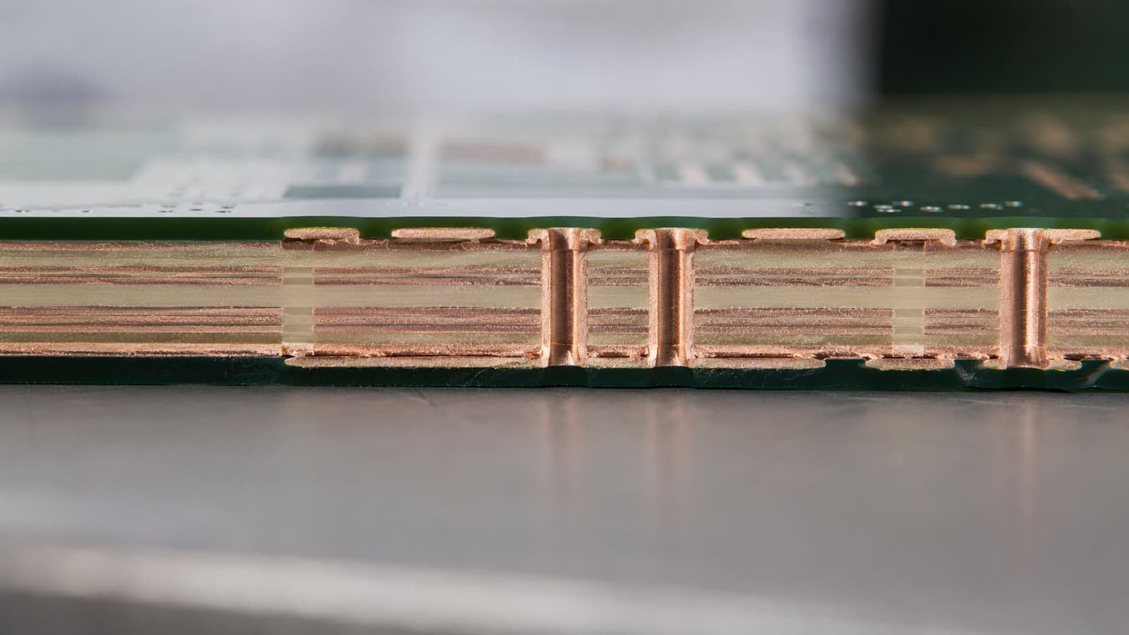
Stackup and Controlled Impedance
Both RO3000 and RO4000 materials can be used in controlled impedance PCB designs.
The stackup should define:
Material series and grade
Dielectric thickness
Copper thickness
RF signal layer
Ground reference plane
Layer count
Final board thickness
Surface finish
Impedance target
Impedance tolerance
The manufacturer should calculate impedance based on the real production stackup. If material thickness changes during production, the impedance result may shift.
For microwave PCB and antenna PCB projects, stackup changes should not be made casually. Even a small change in dielectric thickness can affect RF behavior.
Manufacturing and Process Review
RO4000 Series materials are often considered more practical for many PCB factories to process compared with more specialized high frequency laminates. This can help with lead time, cost control, and repeat production.
RO3000 Series materials may need more careful process review depending on board structure, thickness, layer count, and drilling requirement.
Manufacturing points to check include:
Material availability
Panel size
Drilling quality
Plated through-hole reliability
Copper adhesion
Dimensional stability
Etching tolerance
Lamination requirement
Surface finish
Inspection method
For buyers, manufacturability is part of material selection. A material choice that creates lower yield, longer lead time, or unstable batch production can increase total project cost.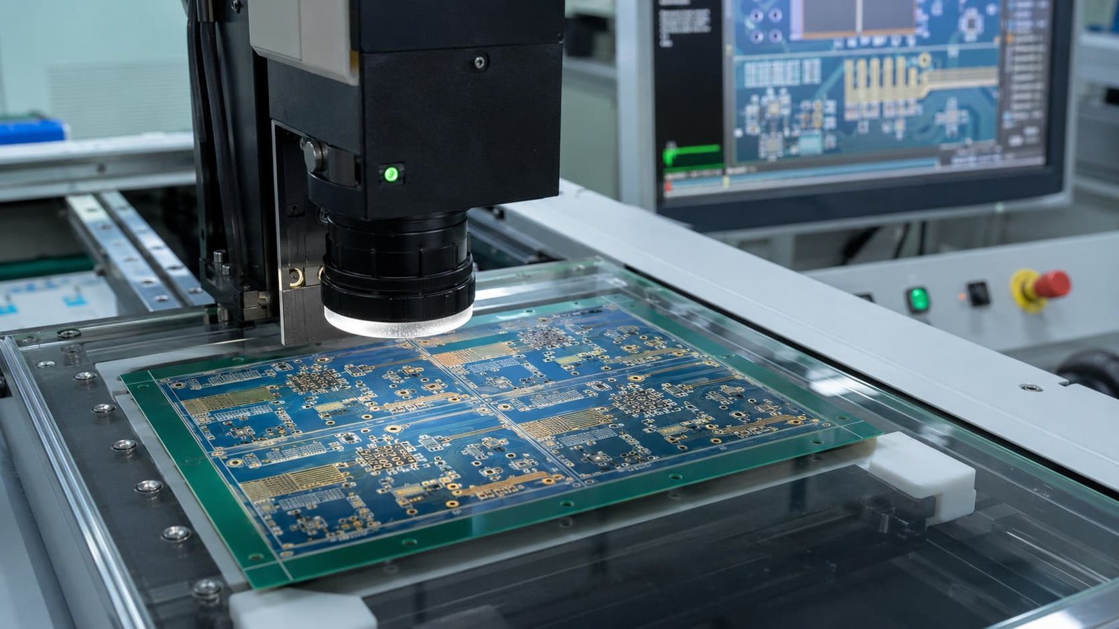
Application-Based Selection
The best way to choose between RO3000 and RO4000 is to start from the application.
For radar, satellite communication, precision antenna systems, and microwave signal paths, RO3000 Series may deserve closer review because signal performance is often more sensitive.
For RF modules, wireless communication devices, industrial RF boards, antenna products, and commercial high frequency designs, RO4000 Series may be a strong practical choice.
A simple decision path is:
Choose RO3000 Series when loss, Dk control, phase behavior, or microwave performance is the main driver.
Choose RO4000 Series when the project needs reliable RF performance with stronger attention to manufacturability, cost, and repeat production.
Still, this is not a fixed rule. The final decision should come from the actual design, not only the application name.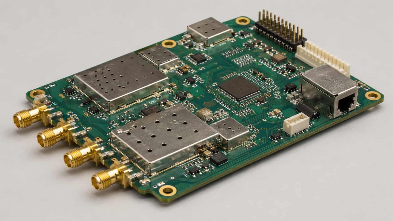
Procurement and Cost Review
From a purchasing point of view, the material decision should include more than laminate price.
Buyers should review:
Material cost
Material availability
Lead time
MOQ or panel utilization
Processing difficulty
Prototype success rate
Batch repeatability
Impedance testing requirement
Final RF test risk
A more expensive material may reduce RF risk in demanding applications. A more practical material may reduce production cost and lead time in commercial projects.
The lowest quotation is not always the lowest project cost. If the material choice causes redesign, failed RF testing, or unstable batch production, the real cost becomes much higher.
What Buyers Should Provide for Quotation
To compare RO3000 Series and RO4000 Series properly, buyers should prepare:
Gerber files
Drill files
PCB stackup
Preferred Rogers material
Working frequency
Controlled impedance requirement
Board thickness
Copper thickness
Surface finish
Quantity
Prototype or batch plan
Application background
Signal loss requirement if available
If the buyer is not sure which series to choose, the working frequency and application background are the most useful starting points. A manufacturer can then review whether RO3000, RO4000, PTFE, Taconic, F4B, or another high frequency material is more reasonable.
Common Mistakes to Avoid
Common mistakes include:
Choosing RO3000 only because it sounds higher performance
Choosing RO4000 only because it is more common
Ignoring Dk and dielectric thickness
Sending files without stackup
Changing material after layout
Comparing only material price
Not checking drilling and plating feasibility
Ignoring batch material availability
No controlled impedance table
Not explaining the application background
These issues often appear during RF testing or repeat production, not visual inspection.
Conclusion
RO3000 Series and RO4000 Series can both be strong Rogers material choices for RF and microwave PCB projects. RO3000 Series is often reviewed for more demanding microwave, radar, antenna, satellite, and low-loss applications. RO4000 Series is often selected when the project needs reliable RF performance, practical manufacturability, and better cost control.
The better choice depends on frequency, loss target, Dk, Df, stackup, impedance, drilling, plated through holes, surface finish, availability, and production plan.
For buyers, the safest approach is to compare the material series together with the PCB design and manufacturing process. The best material is not always the highest-performance material. It is the material that meets the RF requirement and can be produced reliably.