
Aluminum PCB Thermal Design Guide — Selecting the Right Conductivity Grade
The most common aluminum PCB design error is specifying the wrong thermal conductivity grade — either choosing a standard 1.0 W/m·K board for a high-power application that needs 2.0–3.0 W/m·K, or specifying ultra-high thermal grade at additional cost when standard grade is thermally sufficient. This guide covers how to calculate LED junction temperature rise, select the correct thermal conductivity grade, and choose dielectric thickness for your power level.
Home » aluminum PCB dielectric thickness » Aluminum PCB Thermal Design Guide — Selecting the Right Conductivity Grade
Table of Contents
Aluminum PCB Structure and Thermal Path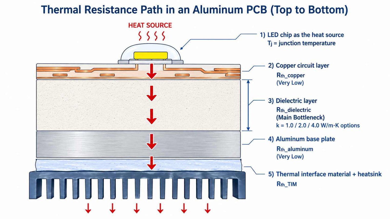
An aluminum PCB (MCPCB — Metal Core PCB) conducts heat from the component through three layers: copper circuit layer → thermally conductive dielectric layer → aluminum base plate. The thermal bottleneck is the dielectric layer: copper and aluminum both have high thermal conductivity, but the dielectric (typically 1.0–4.0 W/m·K) is far lower. Selecting the right dielectric grade determines junction temperature and product lifetime.
Thermal Conductivity Grades
| Grade | Thermal Conductivity | Dielectric Thickness | Typical Application |
|---|---|---|---|
| Standard | 1.0 W/m·K | 100–150 μm | LED lighting (street, panel, downlight) |
| Mid-range | 2.0 W/m·K | 75–100 μm | High-power LED, automotive LED headlight |
| High thermal | 3.0 W/m·K | 50–75 μm | EV power inverter, motor driver, BLDC |
| Ultra thermal | 4.0 W/m·K | 50 μm | High-density power electronics, fast EV charging |
How to Calculate LED Junction Temperature Rise
The thermal resistance of the dielectric layer is: Rth_dielectric = t / (k × A) where t = dielectric thickness (m), k = thermal conductivity (W/m·K), A = component pad area (m²). Junction temperature rise above the aluminum base plate temperature is: ΔTj = P × Rth_dielectric where P = power dissipation (W).
| Parameter | Example Value | Notes |
|---|---|---|
| LED power dissipation (P) | 3W | Electrical power × (1 − luminous efficiency) |
| Dielectric thickness (t) | 0.1mm = 0.0001m | Standard grade |
| Thermal conductivity (k) | 1.0 W/m·K | Standard grade |
| LED pad area (A) | 3×3mm = 9×10⁻⁶ m² | Typical 3W LED footprint |
| Thermal resistance (Rth) | t/(k×A) = 11.1 °C/W | Higher k → lower Rth |
| Temperature rise (ΔT) | P × Rth = 33.3°C | Main thermal bottleneck in standard grade |
| With 2.0 W/m·K grade | Rth = 5.6 °C/W → ΔT = 16.7°C | 50% reduction in junction temp rise |
Worked example: 3W LED on standard grade vs 2.0 W/m·K
A 3W LED with a 3×3mm thermal pad, ambient temperature 40°C, aluminum base plate at 70°C (with adequate heatsink). Standard 1.0 W/m·K grade (100μm dielectric) produces ΔT = 33°C across the dielectric → junction temperature ~103°C. Upgrading to 2.0 W/m·K grade (75μm dielectric) produces ΔT = ~12.5°C → junction temperature ~82.5°C. For a typical LED rated at Tj_max = 125°C, both are within limit — but the 2.0 W/m·K grade provides 42°C more thermal headroom, significantly extending LED lifetime.
When to Choose Each Grade
1.0 W/m·K — Standard LED lighting
Appropriate for general LED street lighting, panel lighting and downlights where power density per LED is moderate (≤3W per device), ambient temperature is controlled, and heatsink area is adequate. The lowest cost option — use this unless thermal calculations show insufficient margin.
2.0 W/m·K — High-power LED and automotive
Required for high-power LED arrays (>3W per device), automotive LED headlights operating at elevated ambient temperatures, and designs where limited heatsink area increases aluminum base plate temperature. Most automotive LED applications specify 2.0 W/m·K as standard.
3.0–4.0 W/m·K — EV power electronics and motor drives
Required for EV power inverters, BLDC motor drivers and fast charging circuits where power density is high and junction temperature margins are tight. For these applications, aluminum PCB manufacturer with 3.0–4.0 W/m·K grade and thinner dielectric (50μm) significantly reduces thermal resistance. Verify voltage withstand (≥2500V AC) when reducing dielectric thickness.
Dielectric Thickness Selection
- Thinner dielectric → lower thermal resistance → lower junction temperature
- Thinner dielectric → lower voltage withstand — verify against circuit isolation requirements
- Standard: 100–150μm → suitable for most LED applications with ≥2500V AC isolation
- High-thermal: 50–75μm → for power electronics where lower Rth is critical — confirm voltage withstand
- Minimum dielectric thickness is constrained by manufacturing process — confirm with manufacturer before specifying below 75μm
Design Checklist for Aluminum PCB
- Calculate Rth_dielectric and ΔTj for your power level before specifying grade
- Confirm Tj_max from component datasheet and provide ≥20°C margin
- Specify thermal conductivity grade on the fabrication drawing — not just ‘aluminum PCB’
- Specify dielectric thickness — default varies by manufacturer if not specified
- Specify copper weight — 1oz standard, 2oz for high-current traces
- Confirm voltage withstand rating matches your isolation requirement
- For automotive applications, specify IATF16949 and halogen-free requirements
Frequently Asked Questions — Aluminum PCB Thermal Design
What thermal conductivity grade should I use for LED aluminum PCB?
What is the thermal resistance of an aluminum PCB dielectric?
Can I use a thinner dielectric to improve thermal performance?
What is the difference between aluminum PCB and FR4 for heat dissipation?
Request a PCB Quote
Upload your Gerber ZIP file and project requirements. Our engineering team will review your PCB material, stackup, impedance needs, surface finish, and production quantity before quoting.
Please prepare:
- Gerber files in ZIP format
- PCB material or stackup requirements
- Controlled impedance notes if available
- Prototype or batch production quantity