Microwave PCB is used in radar electronics because radar systems rely on stable high-frequency signal transmission, low signal loss, controlled impedance, accurate stackup design, and reliable RF manufacturing control.
Compared with standard FR4 PCB, microwave PCB for radar applications often requires low-loss materials such as Rogers, PTFE, Taconic, F4B, or high frequency hybrid stackups. These materials help support better signal integrity, more stable impedance, and improved repeatability in radar modules, antenna systems, RF front-end circuits, and microwave signal processing boards.
For radar PCB projects, material selection is only one part of the process. Stackup design, copper accuracy, drilling quality, plated through-hole reliability, surface finish, and engineering review before production are also critical.
Quick Summary
Microwave PCB for radar electronics is commonly used in radar modules, radar antenna PCBs, RF front-end boards, microwave signal processing circuits, automotive radar, industrial radar, aerospace radar, and test equipment.
Radar PCB performance is affected by dielectric constant, dissipation factor, insertion loss, controlled impedance, board thickness, copper roughness, via structure, and manufacturing tolerance.
Rogers, PTFE, Taconic, F4B, and hybrid stackups are common material options for radar and microwave PCB projects.
Why Radar Electronics Need Microwave PCB
Radar systems transmit and receive high-frequency signals to detect objects, distance, speed, movement, or position. Because radar circuits often operate at microwave or millimeter-wave frequencies, the PCB material and manufacturing process can directly affect signal behavior.
In a radar PCB, traces are not just electrical connections. They act as transmission lines. If the material has high dielectric loss, unstable Dk, poor copper accuracy, or uncontrolled impedance, the radar circuit may suffer from signal loss, reflection, phase instability, or inconsistent testing results.
Microwave PCB is commonly used in radar-related applications such as:
Radar antenna boards
Automotive radar sensors
Industrial radar modules
Aerospace radar electronics
RF front-end circuits
Microwave transceiver boards
Signal processing boards
Test and measurement equipment
Phased-array radar systems
Short-range and long-range radar devices
Key Requirements for Radar Microwave PCB
Low Signal Loss
Low signal loss is one of the most important requirements in radar PCB manufacturing.
Radar circuits depend on accurate signal transmission and reception. If the PCB material has high dielectric loss, the transmitted or received signal may become weaker, which can affect detection performance and system stability.
Low-loss materials are commonly used in microwave PCB and radar PCB projects because they help reduce insertion loss and support more stable high-frequency behavior.
Rogers RO4000 series laminates are described by Rogers as low-loss materials used in microwave and millimeter-wave frequencies, with easier circuit fabrication compared with traditional PTFE materials. This makes them a useful external reference when explaining radar and microwave PCB material selection.
Stable Dielectric Constant
Dielectric constant, also known as Dk, affects signal speed, impedance, wavelength, and circuit dimensions.
For radar PCB applications, stable Dk is important because material variation can affect impedance and phase behavior. If the Dk changes too much between prototype and batch production, radar performance may become inconsistent.
Low Dissipation Factor
Dissipation factor, also known as Df, affects dielectric loss.
For microwave PCB and radar PCB applications, lower Df materials are often preferred because loss increases as frequency becomes higher. If Df is too high, the circuit may experience more signal attenuation.
Controlled Impedance
Controlled impedance is critical for radar microwave PCB.
Radar signal paths often require specific impedance values, commonly 50 ohms for many RF transmission lines. If the impedance is not controlled, signal reflection and mismatch may occur.
Controlled impedance depends on:
Material Dk
Dielectric thickness
Trace width
Copper thickness
Reference ground plane
Layer stackup
Solder mask
Manufacturing tolerance
Radar PCB Material Options
Rogers Materials
Rogers materials are widely used in RF, microwave, radar, antenna, satellite communication, and high frequency PCB applications.
For radar PCB projects, Rogers materials are often considered because they offer stable electrical performance, low-loss options, and strong support for microwave and millimeter-wave circuits.
Different Rogers materials may be suitable for different radar designs. For example, Rogers RO3000 series materials are ceramic-filled PTFE composites intended for commercial microwave and RF applications, while Rogers RO4000 series materials are commonly used for microwave and millimeter-wave circuits.
PTFE Materials
PTFE materials are often selected for demanding microwave PCB and radar PCB applications where low dielectric loss and stable high-frequency performance are important.
PTFE PCB can be suitable for radar modules, microwave antenna boards, RF signal transmission lines, aerospace electronics, and high-frequency test equipment.
However, PTFE materials are more difficult to process than standard FR4. Drilling, plating, bonding, lamination, and dimensional control require experienced high frequency PCB manufacturing capability.
Taconic Materials
Taconic materials can also be considered for radar and microwave PCB applications.
They may be suitable for RF modules, microwave circuits, antenna systems, industrial RF equipment, and radar-related applications where low signal loss and stable dielectric performance are required.
The final Taconic material selection should depend on frequency, Dk, Df, board thickness, impedance requirement, stackup design, and production feasibility.
F4B Materials
F4B materials may be considered for some cost-sensitive radar or RF microwave PCB projects.
For applications that require better high-frequency performance than standard FR4 but need cost control, F4B can sometimes provide a practical balance between performance, availability, and manufacturing efficiency.
However, F4B should still be reviewed carefully based on working frequency, signal loss requirement, impedance control, and customer specifications.
FR4 + High Frequency Hybrid Stackups
Not every radar PCB project requires high frequency material across the entire board.
Some multilayer radar PCB designs may use high frequency materials on critical RF or microwave layers, while using FR4 for supporting layers. This type of hybrid stackup can help balance electrical performance, mechanical strength, and cost.
However, hybrid stackups require careful review because different materials may have different thermal expansion, bonding behavior, and lamination requirements.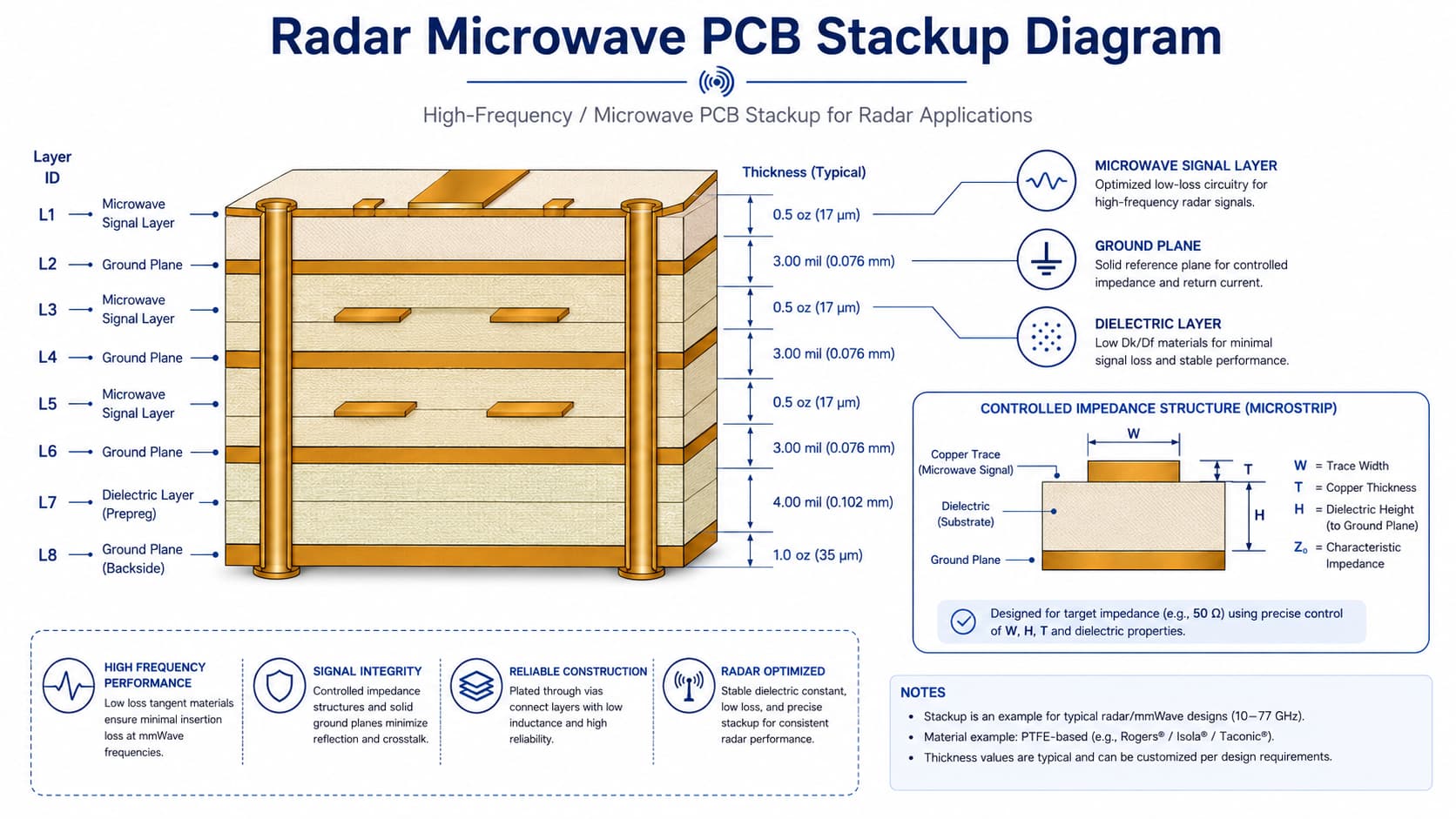
Radar PCB Applications
Automotive Radar PCB
Automotive radar PCB is one of the most common radar PCB application areas. These boards may be used in advanced driver assistance systems, distance detection, speed measurement, blind spot detection, and other sensing functions.
Some automotive radar applications operate in the 76–81 GHz range. Rogers RO4830 Plus laminates are described as engineered for the cap layer on FR-4 multilayer board designs commonly used for 76–81 GHz automotive radar sensor PCB applications.
For automotive radar PCB projects, material stability, laser drilling performance, CAF resistance, dimensional consistency, and high-frequency loss behavior may all become important.
Industrial Radar PCB
Industrial radar systems may be used in level sensing, motion detection, automation equipment, safety systems, smart buildings, factory devices, and short-range detection modules.
For short-range industrial radar applications, Rogers RO4835IND LoPro materials are described as providing low loss and stable RF performance for 60 to 81 GHz industrial radar applications.
Industrial radar PCB manufacturing should focus on low-loss material selection, controlled impedance, stable copper geometry, reliable vias, and repeatable production quality.
Radar Antenna PCB
Radar antenna PCB performance can be strongly affected by material Dk, board thickness, copper pattern accuracy, feed line impedance, and ground plane design.
For radar antenna boards, the PCB material is part of the RF structure. Changing material, thickness, copper finish, or layout geometry may affect frequency behavior, antenna matching, or radiation performance.
Radar antenna PCB projects should review:
Operating frequency
Antenna structure
Material Dk and Df
Board thickness
Feed line impedance
Ground plane design
Copper pattern accuracy
Via placement
Surface finish
Mechanical installation environment
Aerospace and Defense Radar PCB
Aerospace and defense radar electronics often require high reliability, stable microwave performance, and strict manufacturing control.
These projects may require low-loss materials, multilayer microwave PCB structures, controlled impedance, stable plated through holes, thermal reliability, and strong process documentation.
For these applications, the manufacturer should carefully review material availability, stackup feasibility, impedance requirements, drill design, copper thickness, surface finish, and production capability before manufacturing.
Microwave Signal Processing PCB
Radar systems may also include microwave signal processing boards, RF transceiver circuits, mixer circuits, amplifier boards, and filter boards.
These boards may not include the antenna structure directly, but they still require stable RF signal transmission and reliable impedance control.
Manufacturing Challenges in Radar Microwave PCB
Radar PCB manufacturing is more difficult than standard PCB fabrication because high-frequency performance depends on both design and production control.
Important manufacturing challenges include:
Low-loss material handling
Stackup accuracy
Controlled impedance production
Trace width and spacing tolerance
Copper thickness control
Copper roughness consideration
Accurate drilling
Stable plated through holes
Multilayer lamination control
Surface finish consistency
Dimensional stability
Engineering review before production
RF Layout Considerations for Radar PCB
Radar PCB performance is also affected by RF layout.
Important RF layout considerations include short RF paths, continuous ground reference, proper via placement, isolation between sensitive signal paths, and controlled transitions between components, transmission lines, and connectors.
Analog Devices provides RF and mixed-signal PCB layout guidance as a best-practice reference for RF board design and layout. It emphasizes that RF PCB layout should be used together with component, PCB manufacturer, and material guidelines.
Surface Finish for Radar PCB
Surface finish affects solderability, assembly reliability, and sometimes high-frequency behavior.
Common surface finish options may include immersion gold, immersion silver, OSP, HASL, or other customer-specified finishes. For many RF and microwave PCB projects, immersion gold is often considered because it provides a flat surface and stable soldering performance.
However, the final surface finish should be selected based on assembly method, RF requirement, application environment, and customer specification.
What Files Are Needed for Radar PCB Quotation?
To quote a radar microwave PCB project accurately, the manufacturer usually needs complete engineering information.
Recommended files and details include:
Gerber files
Drill files
PCB stackup
Material requirement
Working frequency
Board thickness
Copper thickness
Surface finish
Controlled impedance requirement
Layer count
Quantity
Prototype or batch production requirement
Application background
Special tolerance or reliability requirements
How to Reduce Risk Before Radar PCB Production
To reduce production risk before radar PCB manufacturing, engineers and buyers should confirm:
Working frequency is clear
Material requirement is confirmed
Stackup is reviewed
Controlled impedance values are defined
Copper thickness is confirmed
Surface finish is selected
Drill and via structures are reviewed
Antenna or RF layout requirements are understood
Prototype and batch requirements are clear
Engineering review is completed before production
Conclusion
Microwave PCB plays a critical role in radar electronics, including automotive radar, industrial radar, radar antenna PCB, aerospace radar, RF front-end circuits, and microwave signal processing boards.
For radar PCB projects, material selection, controlled impedance, stackup design, copper accuracy, drilling quality, plated through-hole reliability, surface finish, and manufacturing tolerance all affect final performance.
Rogers, PTFE, Taconic, F4B, and high frequency hybrid stackups can all be considered depending on frequency, signal loss requirement, radar application, cost target, and manufacturing feasibility.