Taconic Advanced Dielectric Division produces a family of PTFE-based high frequency PCB laminates that have been used in RF and microwave applications for decades. Taconic materials are less widely specified than Rogers in mainstream defense and aerospace programs, but they offer genuine technical alternatives for engineers who encounter them in their supply chain or who are evaluating Taconic alongside Rogers for commercial RF applications.
As a direct high frequency PCB factory producing both Taconic and Rogers materials, we build Taconic TLY-5, TLP-5, TLY-3, RF-35, RF-60A, and CER-10 in regular production. This guide covers the Taconic material portfolio, the technical differences between grades, how Taconic compares to Rogers equivalents, and manufacturing process requirements.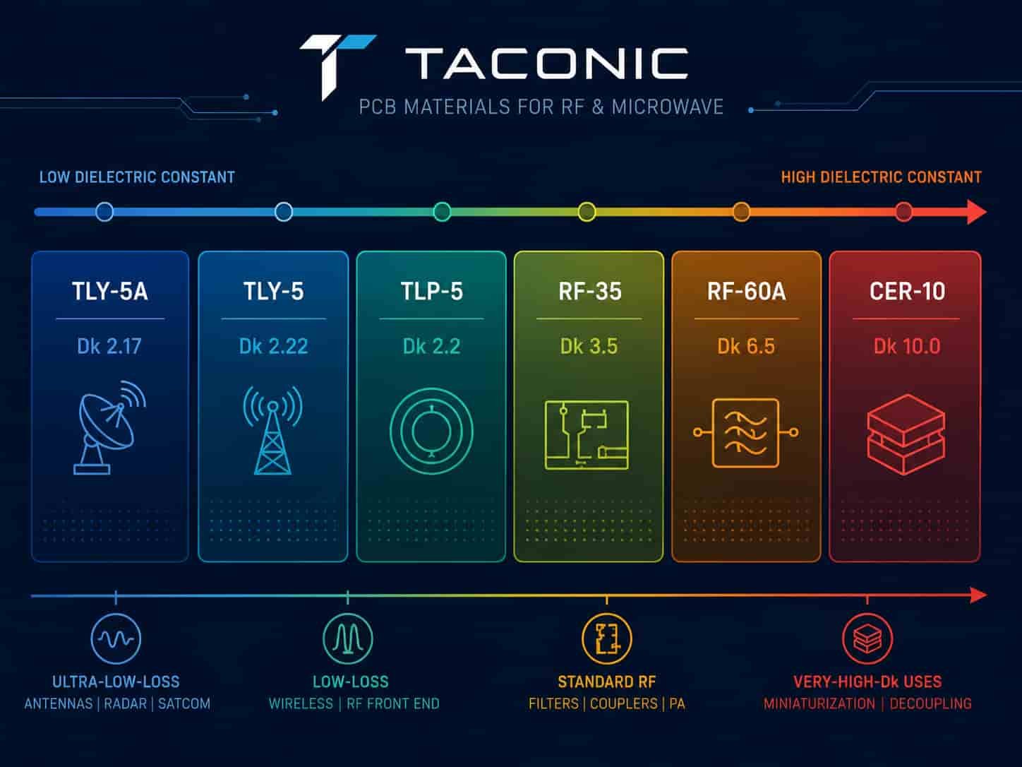
Quick Summary
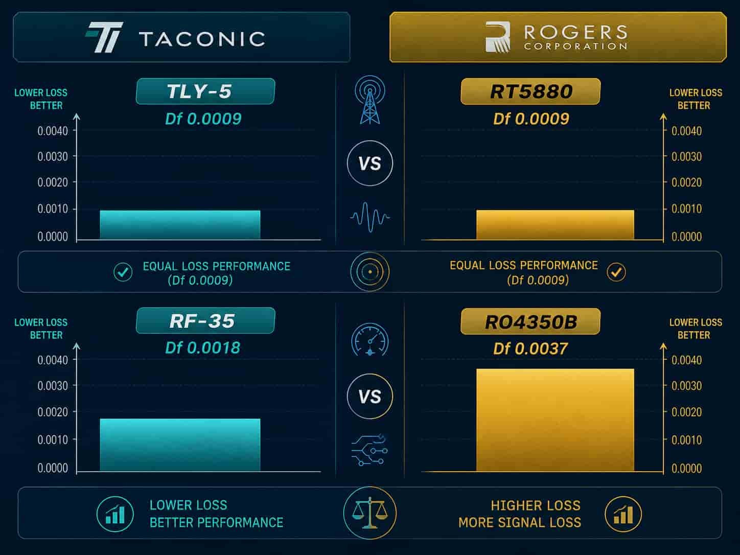
Key point: Taconic TLY-5 and TLP-5 match Rogers RT5880 in both Dk (2.2) and Df (0.0009) — they are genuine equivalents for many commercial RF applications. Taconic RF-35 (Dk 3.5, Df 0.0018) has lower Df than Rogers RO4350B (Df 0.0037) at comparable Dk, making it a viable alternative for commercial designs below 20 GHz where Rogers certification is not required. For aerospace and defense programs that specify Rogers by grade, Taconic substitution requires customer approval. For commercial wireless, VSAT, and industrial RF projects, Taconic is a technically sound and often cost-competitive option.
Taconic Material Portfolio: All Grades Explained
TLY-5A, TLY-5, and TLP-5 — Ultra-Low Loss PTFE
The TLY-5 family is Taconic’s lowest-loss material group, directly comparable to Rogers RT5880 in dielectric properties. These are woven glass PTFE composites with Dk in the 2.17–2.22 range and Df of 0.0009 — matching Rogers RT5880 on both parameters.
- TLY-5A: Dk 2.17, Df 0.0009 — lowest Dk in Taconic portfolio
- TLP-5: Dk 2.20, Df 0.0009 — exact match to Rogers RT5880 Dk
- TLY-5: Dk 2.22, Df 0.0009 — slight Dk variation from TLP-5
- Available thicknesses: 0.09mm, 0.13mm, 0.25mm, 0.51mm, 0.79mm, 1.58mm, 2.36mm — custom thicknesses available
- Processing: PTFE — requires hole wall activation, PTFE-specific drill parameters, maximum 2 lamination cycles
- Applications: EW receivers (2–18 GHz), SIGINT, W-band circuits, ultra-low-loss microwave feed networks, applications currently using Rogers RT5880
Taconic TLY-5 vs Rogers RT5880: Both have Dk 2.2 and Df 0.0009. The technical properties are equivalent for most RF applications. The primary difference is qualification history: Rogers RT5880 has more documented use in aerospace and defense programs. For commercial applications, TLY-5/TLP-5 is a direct technical substitute.
TLY-3 — Low Loss PTFE, Slightly Higher Dk
TLY-3 is a low-loss PTFE material with Dk 2.33 and Df 0.0012, directly comparable to Rogers RT5870. It is used where a slightly higher Dk than TLY-5 is needed — for example, when circuit geometry requires slightly smaller antenna element dimensions at a given frequency.
- Dk: 2.33, Df: 0.0012
- Rogers equivalent: RT5870 (Dk 2.33, Df 0.0012) — identical properties
- Available thicknesses: same standard range as TLY-5
- Applications: low-loss RF circuits requiring slightly higher Dk than TLY-5, compact antenna designs
TLT-0 Through TLT-6 — Mid-Range Dk PTFE
The TLT series covers a Dk range from 2.45 to 2.65 with Df from 0.0015 to 0.0021. These materials fill the gap between the ultra-low Dk of TLY-5 and the higher-Dk RF-35. They are used in designs where a Dk between 2.5 and 2.7 is required for specific circuit impedance or antenna element sizing.
- Dk range: 2.45–2.65 depending on grade
- Df range: 0.0015–0.0021
- Available thicknesses: 0.4mm, 0.13mm, 0.25mm, 0.51mm, 0.79mm, 1.58mm, 3.18mm
- Applications: RF circuits requiring mid-range Dk, specific transmission line geometries
TLA-6 — PTFE at Dk 2.65
TLA-6 (Dk 2.65, Df 0.0017) is a PTFE material at the upper end of the low-Dk range. It is available in 0.76mm and 1.45mm standard thicknesses.
- Dk: 2.65, Df: 0.0017
- Standard thicknesses: 0.76mm, 1.45mm
- Applications: RF circuits requiring Dk around 2.65 — fills the gap between TLT series and RF-35
RF-35 — General Purpose RF Laminate
Taconic RF-35 (Dk 3.5, Df 0.0018) is Taconic’s most widely used general-purpose RF material. Its Dk of 3.5 is close to Rogers RO4350B (Dk 3.48), but its Df of 0.0018 is significantly lower — about half of RO4350B’s Df of 0.0037. This makes RF-35 a technically competitive alternative to RO4350B for many commercial RF applications.
- Dk: 3.5, Df: 0.0018 — better Df than Rogers RO4350B at similar Dk
- Available thicknesses: 0.25mm, 0.51mm, 0.76mm, 1.52mm
- Processing: PTFE — same PTFE hole wall activation and lamination requirements as TLY-5
- Rogers comparison: lower Df than RO4350B, but RO4350B has FR4-compatible processing which RF-35 does not
- Applications: commercial RF PCB below 20 GHz, VSAT ground terminals, base station feed networks, industrial RF equipment
RF-35 vs RO4350B: RF-35 has lower Df (0.0018 vs 0.0037) — a genuine RF performance advantage. However, RO4350B processes on FR4-compatible equipment without PTFE activation. RF-35 requires full PTFE process including hole wall activation. For a factory that already runs PTFE, the process difference is minimal. For a factory that only does FR4, RO4350B is far easier to produce reliably.
RF-60A — High Dk RF Laminate
Taconic RF-60A (Dk 6.5, Df 0.0038) is a high dielectric constant PTFE material for applications requiring compact circuit dimensions. Higher Dk reduces the physical size of resonant structures, patch antennas, and filters at a given frequency.
- Dk: 6.5, Df: 0.0038
- Available thicknesses: 0.25mm, 0.64mm, 0.79mm, 1.27mm, 1.52mm, 3.18mm
- Processing: PTFE
- Rogers comparison: similar function to Rogers RO3006 (Dk 6.15) — slightly higher Dk, comparable Df
- Applications: compact patch antenna arrays, high-Dk bandpass filters, miniaturized RF modules where physical size is constrained
CER-10 — Very High Dk for Maximum Miniaturization
Taconic CER-10 (Dk 10.0, Df 0.0035) provides the highest dielectric constant in the Taconic portfolio, enabling the most compact resonant circuit designs. The Dk of 10.0 reduces antenna element dimensions by approximately 30% compared to Dk 3.5 at the same frequency.
- Dk: 10.0, Df: 0.0035
- Available thicknesses: 0.28mm, 0.64mm, 0.76mm, 1.19mm, 1.58mm, 3.18mm
- Processing: PTFE ceramic
- Rogers comparison: equivalent to Rogers RO3010 (Dk 10.2) in function and application
- Applications: highly compact patch antennas, phased array elements where aperture size is constrained, miniaturized filter designs
Taconic vs Rogers: Direct Comparison
Engineers often ask how Taconic compares to Rogers for specific applications. The following covers the most common cross-material questions.
Taconic TLY-5 / TLP-5 vs Rogers RT5880
- Dk: TLP-5 = 2.20, RT5880 = 2.20 — identical
- Df: both = 0.0009 — identical
- Processing: both PTFE — identical process requirements
- Thicknesses: comparable ranges — both available to 0.127mm equivalent
- Verdict: technically equivalent for most commercial RF applications. For aerospace and defense programs with Rogers RT5880 specified on the drawing, Taconic substitution requires written customer approval.
Taconic TLY-3 vs Rogers RT5870
- Dk: both 2.33 — identical
- Df: both 0.0012 — identical
- Processing: both PTFE — identical
- Verdict: direct technical equivalent
Taconic RF-35 vs Rogers RO4350B
- Dk: RF-35 = 3.50, RO4350B = 3.48 — essentially identical
- Df: RF-35 = 0.0018, RO4350B = 0.0037 — RF-35 has 51% lower Df
- Processing: RF-35 is PTFE (requires activation), RO4350B is hydrocarbon ceramic (FR4-compatible)
- Tg: RF-35 PTFE has no practical Tg, RO4350B >280°C — both adequate for aerospace operating temperatures
- Verdict: RF-35 has better electrical performance (lower Df). RO4350B is easier to process in most factories. For a factory with PTFE capability, RF-35 is a technically superior option at similar cost. For factories without PTFE equipment, RO4350B is the practical choice.
Taconic RF-60A vs Rogers RO3006
- Dk: RF-60A = 6.5, RO3006 = 6.15 — RF-60A slightly higher
- Df: RF-60A = 0.0038, RO3006 = 0.0020 — RO3006 has lower Df
- Verdict: RO3006 has better RF loss performance. RF-60A may be preferred when slightly higher Dk is needed for specific circuit geometry.
Taconic CER-10 vs Rogers RO3010
- Dk: CER-10 = 10.0, RO3010 = 10.2 — very similar
- Df: CER-10 = 0.0035, RO3010 = 0.0022 — RO3010 has lower Df
- Verdict: RO3010 has better electrical performance. CER-10 is an alternative when RO3010 availability is limited.
Manufacturing Process for Taconic PCB
All Taconic materials in the TLY, TLP, RF, and CER series are PTFE-based. They share the same manufacturing process requirements as Rogers PTFE materials — specifically Rogers RO3003 and RT5880. A factory that can produce Rogers RO3003 reliably can produce Taconic TLY-5 and RF-35 with the same process.
PTFE Hole Wall Activation
PTFE is a chemically inert material that does not bond readily to copper during electroless copper plating. Before plating, the drilled hole wall must be chemically or physically activated to create a bondable surface.
- Sodium naphthalene (wet chemical): etches the PTFE surface, creating polar functional groups that accept copper deposition — effective but requires handling of hazardous chemicals
- Plasma activation: RF plasma treatment activates the PTFE surface — cleaner process, widely used in modern factories
- Without activation: electroless copper will not adhere reliably to PTFE hole walls — via reliability will fail under thermal cycling
- Our factory: plasma activation process used for all Taconic PTFE materials
Drilling Parameters
- Spindle speed: lower than FR4 — PTFE is soft and generates more heat at high RPM, causing hole wall smearing
- Feed rate: lower than FR4 — prevents PTFE deformation at the drill entry
- Entry and backing materials: PTFE-specific cover and backer boards to prevent surface burring
- Hole quality: confirm hole wall smoothness and roundness — PTFE drilling defects are more common than FR4 if parameters are not optimized
Lamination
- Temperature profile: PTFE-specific press temperature — different from FR4
- Pressure: controlled to prevent PTFE flow — PTFE softens under heat and can deform if pressure is not managed
- Maximum cycles: 2 press cycles for all Taconic PTFE materials — same limit as Rogers PTFE
- Bonding film: Taconic uses tacBOND or equivalent PTFE-compatible bonding film for multilayer construction
Controlled Impedance for Taconic PCB
- Impedance calculation: use confirmed production Dk from the material certificate — Taconic Dk values have the same tolerance ranges as Rogers (typically ±0.02 to ±0.05 depending on grade)
- TDR verification: same as Rogers — impedance coupon measured by TDR on every production lot
- Standard tolerance: ±10% for traces ≥50Ω; ±5Ω for traces <50Ω
- Advanced tolerance: ±8% available
Application Selection: When to Use Taconic vs Rogers
Use Taconic When:
- The design is commercial and Rogers certification is not specified — Taconic is technically equivalent to the Rogers grade at comparable or lower cost
- The customer has specified Taconic by grade on the design drawing
- TLY-5 or RF-35 is already qualified on an existing design that is being repeated — no reason to change
- RF-35 is being considered as a lower-loss alternative to RO4350B for a commercial application — RF-35’s lower Df is a genuine advantage
Use Rogers When:
- The program specification, fabrication drawing, or BOM specifies Rogers by grade — substitution requires written customer approval
- The application is aerospace or defense with MIL-PRF-31032 or Rogers-certified material documentation requirements
- The design uses Rogers hydrocarbon materials (RO4350B, RO4003C) — Taconic has no direct equivalent to the FR4-compatible Rogers hydrocarbon series
- Long-term supply continuity on a defense program — Rogers has more extensive global stocking
Factory perspective: We build both Taconic and Rogers PTFE materials using the same PTFE process line. For commercial customers asking about Taconic vs Rogers, our honest guidance is: TLY-5 and TLP-5 are technically equivalent to RT5880 for most commercial applications. RF-35 has lower Df than RO4350B for the same Dk. If your design is commercial and performance is the priority, Taconic RF-35 is worth considering. If Rogers documentation is required or the program specifies Rogers, stay with Rogers.
For Rogers material selection guidance, see Rogers PCB Material Selection Guide for RF and Microwave Applications. For F4B and ZY Chinese alternative materials, see F4B PCB Material Guide and ZY High Frequency PCB Material.
Taconic PCB Materials Available at Riching PCB
We hold the following Taconic materials in regular production inventory:
- Taconic TLY-5A: 0.09mm, 0.13mm, 0.25mm, 0.51mm, 0.79mm, 1.58mm, 2.36mm
- Taconic TLP-5: same standard thicknesses as TLY-5A
- Taconic TLY-5: same standard thicknesses
- Taconic TLY-3: standard range
- Taconic RF-35: 0.25mm, 0.51mm, 0.76mm, 1.52mm
- Taconic RF-60A: 0.25mm, 0.64mm, 0.79mm, 1.27mm, 1.52mm, 3.18mm
- Taconic CER-10: 0.28mm, 0.64mm, 0.76mm, 1.19mm, 1.58mm, 3.18mm
All Taconic orders go through the same PTFE manufacturing process as Rogers RO3003 and RT5880: plasma activation, PTFE-specific drill parameters, controlled lamination, and TDR impedance verification on every production lot.
What to Prepare for Taconic PCB Quotation
- Gerber files and NC drill files
- Taconic material grade and thickness — or operating frequency for material recommendation
- Complete stackup with layer sequence and copper weight
- Controlled impedance requirements
- Layer count and board thickness
- IPC Class requirement — Class 2 or Class 3
- Surface finish — ENIG preferred for most Taconic RF applications
- Application type — commercial or defense/aerospace
- Quantity
For a complete file checklist, see What Files Are Needed for a High Frequency PCB Quotation?.
Conclusion
Taconic PCB materials offer genuine technical alternatives to Rogers across the full high frequency laminate Dk range. TLY-5 and TLP-5 match Rogers RT5880 in both Dk and Df — they are direct equivalents for commercial RF applications. RF-35 provides lower Df than Rogers RO4350B at similar Dk, making it a technically strong option for commercial RF PCB below 20 GHz. The critical manufacturing requirement — PTFE hole wall activation and PTFE-specific drilling and lamination — is the same for Taconic as for Rogers PTFE materials.
As a direct high frequency PCB factory producing both Taconic and Rogers materials in the same PTFE process line, we can build whichever material your design requires. If you are evaluating Taconic as an alternative to Rogers for a commercial application, our engineering team can confirm technical equivalence for your specific design and application before production.