
Taconic PCB materials are used in high frequency circuit boards where standard FR4 may not provide enough signal stability, low-loss performance, or impedance consistency. In RF PCB, microwave PCB, antenna PCB, radar electronics, satellite communication, and wireless infrastructure projects, the laminate is part of the signal path, not just a mechanical base.
For buyers, the key question is simple: does the design really need a high frequency material such as Taconic, and can the PCB factory process it reliably?
Taconic’s Advanced Dielectric Division has long focused on microwave circuit board materials, and its laminate substrates are used in communication systems, collision-avoidance and radar systems, cellular communications, and GPS-related applications. You can review Taconic’s official background on its Advanced Dielectric Division page.
For custom projects, Riching PCB supports high frequency PCB manufacturing, RF PCB manufacturing, microwave PCB manufacturing, antenna PCB manufacturing, and Taconic materials for RF and microwave applications.
Quick Summary
Taconic PCB materials are commonly used for RF modules, microwave circuits, antenna systems, radar electronics, satellite communication, GPS systems, wireless infrastructure, and test equipment.
They are often considered when a project needs lower signal loss, stable dielectric performance, and better high frequency behavior than standard FR4.
The right material should be selected based on working frequency, Dk, Df, board thickness, controlled impedance, stackup structure, and manufacturing feasibility.
Before production, the PCB manufacturer should review Gerber files, stackup, material requirement, drill files, copper thickness, surface finish, impedance requirement, and quantity.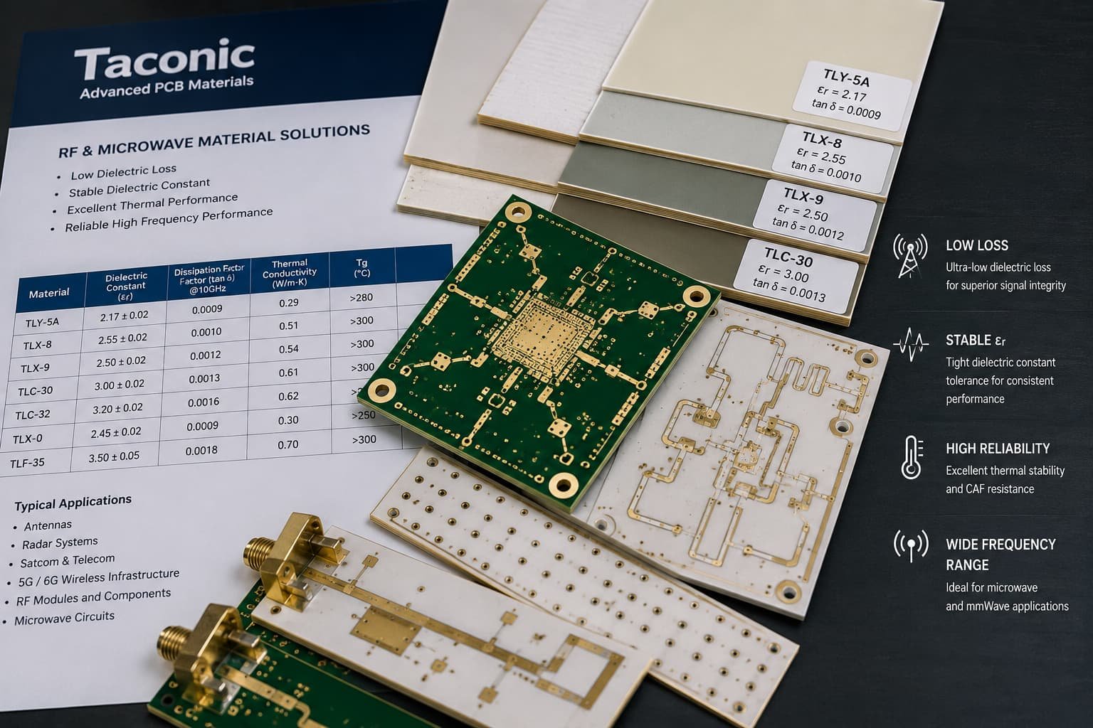
Where Taconic PCB Materials Are Used
Taconic materials are often selected for projects where RF performance and material stability matter more than the lowest material cost.
Common applications include:
RF modules
Microwave communication boards
Antenna systems
Radar electronics
GPS-related devices
Satellite communication
Industrial RF equipment
Test and measurement devices
Wireless infrastructure
For example, a simple control board may work well with FR4. But a microwave antenna board, radar signal path, or RF communication module may require a laminate with more stable Dk, lower Df, and better high frequency behavior.
AGC’s RF/Microwave Laminates page is a useful external reference for the type of applications where RF and microwave laminates are commonly used, including high performance RF/microwave PCBs, phased-array radar antennas, and automotive radar sensor antennas.
Why Material Selection Matters
In high frequency PCB manufacturing, material choice affects more than price. It can influence impedance, signal loss, insertion loss, thermal behavior, drilling quality, and repeatability between prototype and batch production.
For Taconic PCB projects, engineers usually review:
Working frequency
Dk and Df values
Board thickness
Copper thickness
Layer count
Controlled impedance
RF trace geometry
Ground plane structure
Surface finish
Application environment
A material that works well for one RF module may not be the best choice for a radar antenna or satellite communication board. The material should be selected around the real circuit requirement, not only the material name.
For a broader material comparison, you can also review How to Choose High Frequency PCB Materials for RF Applications and How Dk and Df Affect High Frequency PCB Performance.
Dk and Df in Taconic PCB Projects
Dk, or dielectric constant, affects impedance, wavelength, trace geometry, antenna size, and signal speed.
Df, or dissipation factor, affects dielectric loss. In RF and microwave applications, lower Df is usually preferred because signal loss becomes more noticeable as frequency increases.
For Taconic PCB projects, Dk and Df should be reviewed together. Choosing a material only by Dk is risky. A design may also need low Df, stable thickness, suitable copper type, good dimensional behavior, and a manufacturable stackup.
This is especially true for:
Antenna feed lines
Radar signal paths
RF filters
Microwave communication boards
Satellite communication modules
Test equipment signal paths
Stackup Review Before Manufacturing
The stackup should be confirmed before manufacturing a Taconic PCB. For RF and microwave designs, the stackup is part of the electrical design.
A useful stackup review should include:
Material type
Layer count
Dielectric thickness
Copper thickness
Ground plane location
Signal layer position
Controlled impedance target
Final board thickness
Surface finish
Via structure
If the dielectric thickness changes during production, the impedance may change. If the copper thickness changes, trace geometry and loss behavior may also change.
For multilayer RF boards or hybrid stackups, the review becomes more important. Taconic material may be combined with FR4 or other materials in some designs, but material compatibility, lamination process, drilling behavior, and plated through-hole reliability must be checked before production.
For related stackup planning, see RF PCB Stackup Design: Key Factors Before Manufacturing and FR4 + Rogers Hybrid PCB Stackup. The same engineering logic applies when reviewing high frequency hybrid stackups with other RF materials.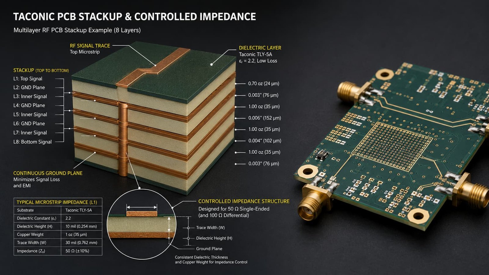
Manufacturing Considerations
Taconic PCB manufacturing should be reviewed before production, especially when the design includes RF traces, dense ground vias, microwave paths, or controlled impedance.
Key manufacturing points include:
Material handling
Drilling quality
Hole wall preparation
Copper plating
Etching accuracy
Trace width control
Lamination process
Dimensional stability
Surface finish
Final inspection
The manufacturer should also check whether the board is single-sided, double-sided, multilayer, or hybrid. A simple two-layer RF board may mainly need trace accuracy and material thickness control. A multilayer microwave PCB may require deeper review of lamination, registration, vias, and impedance testing.
Controlled Impedance
Many Taconic PCB projects require controlled impedance.
Impedance depends on material Dk, dielectric thickness, trace width, copper thickness, reference plane, solder mask, and manufacturing tolerance. If the design includes 50-ohm RF traces, antenna feed lines, or microwave signal paths, impedance should be calculated and reviewed before fabrication.
The quotation request should clearly state:
Target impedance
Tolerance requirement
Layer location
Trace structure
Reference plane
Impedance test requirement if needed
Controlled impedance is not something to fix after production. It must be built into the stackup and manufacturing plan from the beginning.
Surface Finish Selection
Surface finish should match the assembly method and RF requirement.
Common options include ENIG, immersion silver, OSP, HASL, lead-free HASL, hard gold for contact areas, and customer-specified finishes.
ENIG is commonly used in many RF and microwave PCB projects because it provides a flat surface and stable solderability. Immersion silver may be considered for some RF-sensitive applications, while OSP and HASL should be reviewed carefully based on storage, assembly, and surface flatness requirements.
What Buyers Should Prepare for Quotation
A Taconic PCB quote will be more accurate if the buyer provides complete technical details from the start.
Recommended files and information include:
Gerber files
Drill files
PCB stackup
Taconic material requirement
Board thickness
Copper thickness
Surface finish
Controlled impedance requirement
Layer count
Quantity
Working frequency
Application background
Special reliability requirements
If the exact material is not confirmed, the working frequency and application background are especially useful. The manufacturer can review whether Taconic, Rogers, PTFE, F4B, or another high frequency material is more suitable.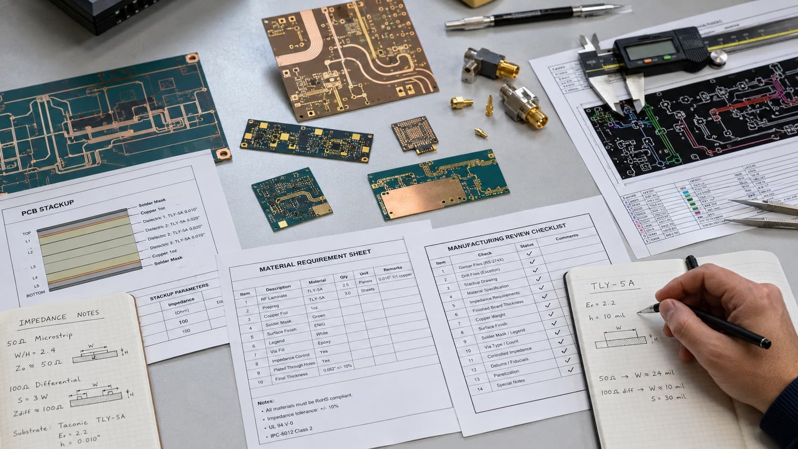
Conclusion
Taconic PCB materials are useful for RF and microwave applications where signal performance, low loss, stable impedance, and repeatable manufacturing matter.
They may be used in RF modules, microwave circuits, antenna systems, radar electronics, satellite communication, GPS systems, wireless infrastructure, and test equipment. But material selection alone is not enough. Stackup, drilling, plated through holes, surface finish, copper control, and impedance review all affect the final result.
For Taconic PCB projects, early engineering review helps reduce material selection risk, quotation changes, and production problems before prototype or batch manufacturing.