
Taconic and Rogers PCB materials are both used in RF PCB, microwave PCB, antenna PCB, radar electronics, wireless communication, satellite communication, and other high-frequency circuit board projects. They are usually compared when standard FR4 cannot meet the required signal loss, impedance stability, or dielectric performance.
The right choice is not simply about which brand is better. A practical material decision depends on working frequency, Dk, Df, dielectric thickness, copper type, stackup design, controlled impedance target, manufacturing difficulty, availability, and project cost.
For buyers, the best approach is to compare materials based on the real application. A radar board, antenna feed network, wireless module, and industrial RF board may all require different material priorities.
Quick Summary
- Taconicand Rogers materials are both used for RF and microwave PCB projects where signal performance matters more than standard FR4 capability.
- Rogers materialsare widely recognized and often selected for their strong engineering documentation, broad material families, and common use in RF PCB design.
- Taconic materialsare also well established in RF and microwave applications and may be considered when their electrical properties, availability, thickness options, or project requirements match the design.
- The final decision should be based on RF performance, stackup feasibility, impedance control, manufacturing process, cost target, and prototype-to-batch consistency.
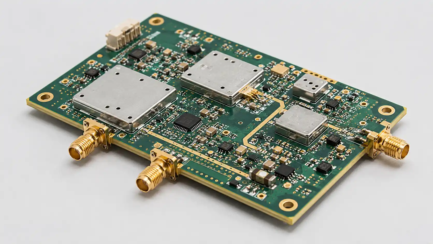
Where Taconic and Rogers Materials Are Used
Both material families appear in demanding high-frequency applications.
Common applications include:
- RF modules
- Microwave communication boards
- Antenna PCBs
- Radar electronics
- Satellite communication circuits
- Wireless infrastructure
- Industrial RF devices
- RF test equipment
- Aerospace RF modules
- High-frequency signal boards
In these projects, the laminate affects more than mechanical support. It influences impedance, insertion loss, antenna behavior, phase stability, copper pattern accuracy, and final test results.
This is why material comparison should happen before production — not after the prototype fails RF testing.
Rogers PCB Materials: Why Buyers Choose Them
Rogers materials are widely used in RF and microwave PCB projects because many engineers are already familiar with their material families.
Buyers often choose Rogers materials for:
- Recognized RF material options with extensive application notes
- Common use in antenna and microwave designs
- Strong industry acceptance and design community support
- Well-documented Dk and Df values across frequency
- Wide use in controlled impedance designs
- Clear communication between designers and PCB manufacturers
For many projects, Rogers materials make engineering communication simpler. When a customer specifies RO4003C, RO4350B, RO3003, or RT/duroid, the material direction is already clearer than a vague “high-frequency material” request. Full material datasheet references are available at rogerscorp.com.
Still, Rogers material selection should not be automatic. The selected grade must match the real RF requirement and the manufacturer’s production process.
Taconic PCB Materials: When They Are Considered
Taconic materials are also used in RF, microwave, antenna, and communication PCB projects. They may be reviewed when their dielectric properties, material thickness, cost structure, or availability fit the project requirement. Full laminate specifications are available at taconic-add.com.
Taconic materials may be considered for:
- Microwave signal boards
- RF communication circuits
- Antenna systems
- Industrial RF equipment
- Radar-related circuits
- High-frequency test boards
- Low-loss transmission paths
For some projects, Taconic may provide a practical option depending on the selected material grade and production requirement. The decision should be based on datasheet values, stackup feasibility, and manufacturing review — not brand preference alone.
Dk and Df Comparison
Dk and Df are typically the first technical values engineers compare.
Dk affects impedance, trace width, wavelength, antenna element size, and RF layout geometry. Df affects dielectric loss and signal attenuation. In high-frequency designs, both values must be reviewed together with thickness, copper type, and production tolerance.
A proper material comparison should include:
- Nominal Dk value
- Dk tolerance across temperature and frequency
- Df value
- Frequency condition of the datasheet values
- Dielectric thickness
- Copper type and roughness
- Signal loss target
- Application requirement
A material with a similar Dk may still behave differently in production if thickness, copper roughness, or process control differs. For microwave PCB, the full RF path matters more than any single datasheet value. The Rogers MWI-2021 calculator can help verify whether a given material, thickness, and trace width combination meets the impedance target before committing to fabrication.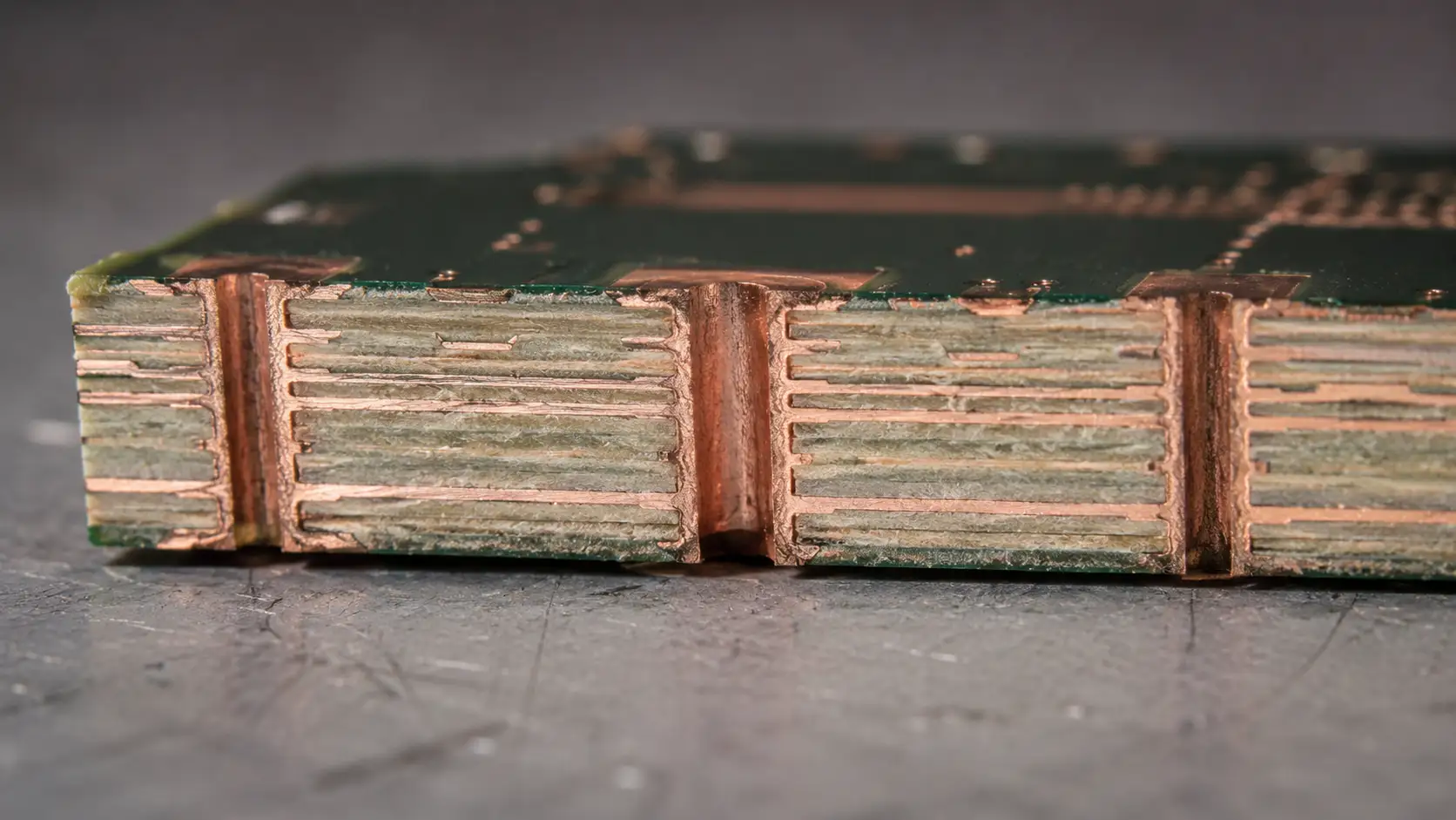
Stackup and Controlled Impedance
Taconic and Rogers PCB projects often require controlled impedance. The stackup should define:
- Material type
- Layer count
- Dielectric thickness
- Copper thickness
- RF signal layer
- Ground reference plane
- Final board thickness
- Controlled impedance target and tolerance
- Surface finish
- Via structure
The manufacturer should calculate impedance based on the real production stackup, as defined in IPC-2141A. If the design assumes one dielectric thickness but production uses another, impedance may shift.
For antenna PCB, radar PCB, and microwave PCB, stackup changes should not be made casually. Even small adjustments may affect RF behavior, antenna tuning, or signal loss.
Manufacturing and Processing Review
Material performance is only useful if the PCB can be manufactured reliably.
Before choosing Taconic or Rogers, the manufacturer should review:
- Material availability and lead time
- Panel size options
- Drilling behavior
- Plated through-hole reliability
- Copper adhesion
- Etching tolerance
- Dimensional stability
- Lamination requirement
- Surface finish compatibility
- Inspection method
- Batch repeatability
Some materials may be easier for a specific factory to process due to experience, tooling, or supply chain familiarity. This should be part of the material decision. A material that performs well on paper may create production risk if the factory has limited process experience with it.
Cost and Availability
Cost comparison should include more than the laminate price alone.
Buyers should review:
- Material price
- Lead time
- Minimum order quantity
- Available thickness options
- Panel utilization efficiency
- Prototype schedule
- Batch supply stability
- Processing difficulty
- Yield risk
- Impedance test requirement
A lower material price may not reduce total project cost if it increases fabrication difficulty, test failure risk, or repeat production uncertainty. For B2B projects, repeatability and stable supply are often more valuable than a one-time price saving.
Application-Based Selection
The best way to choose between Taconic and Rogers materials is to start from the real application requirement.
For radar, satellite communication, microwave signal paths, and precision antenna designs, low loss, Dk control, and phase behavior may drive the decision.
For RF modules, industrial RF equipment, wireless boards, and commercial communication products, manufacturability, material availability, and cost control may matter more.
A practical review should ask:
- What is the working frequency?
- How long is the RF signal path?
- Is insertion loss tightly budgeted?
- Is antenna tuning sensitive to Dk variation?
- Is controlled impedance required?
- Will the board move to batch production?
- Can the material be sourced consistently?
The answer may point to Rogers, Taconic, PTFE, F4B, or a hybrid stackup depending on the design and production requirement.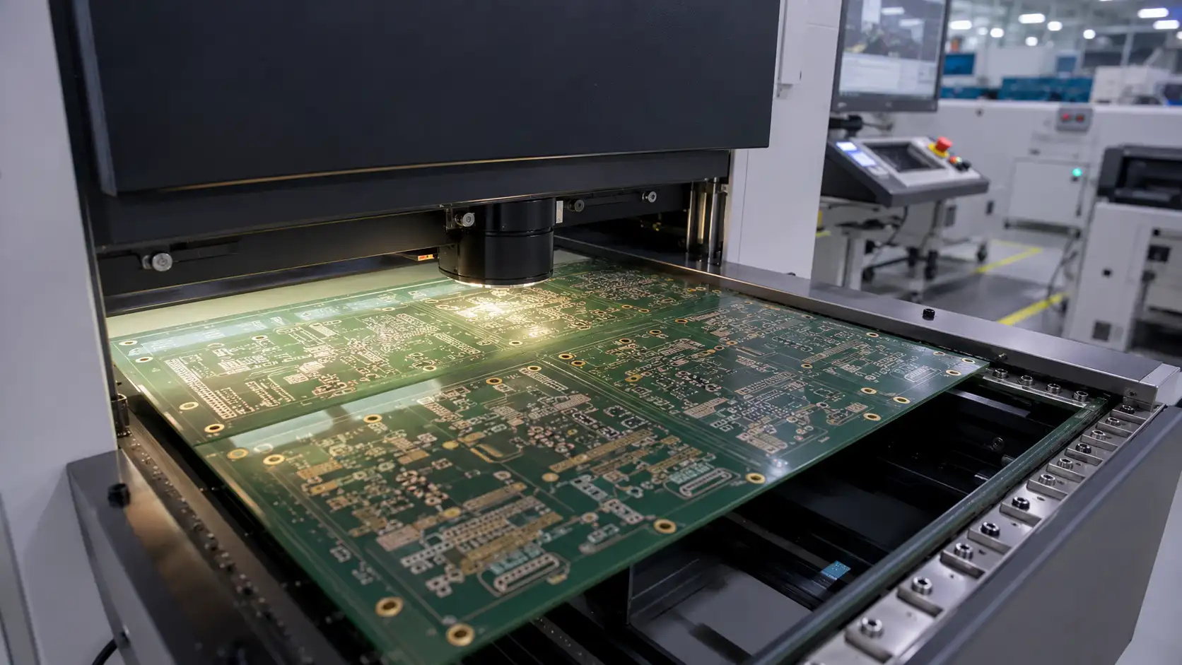
What Buyers Should Provide for Quotation
To compare Taconic and Rogers materials properly and receive a useful quotation, buyers should prepare:
- Gerber files
- Drill files
- PCB stackup
- Preferred material (if available)
- Working frequency
- Controlled impedance requirement
- Board thickness
- Copper thickness
- Surface finish
- Quantity
- Prototype or batch plan
- Application background
- Signal loss requirement (if available)
If the buyer is not yet sure which high-frequency material to choose, working frequency and application background are the most useful starting points. The manufacturer can then review practical material options instead of guessing.
Common Mistakes to Avoid
Common mistakes when comparing Taconic and Rogers materials:
- Choosing material based on brand name alone
- Comparing only Dk while ignoring Df
- Ignoring dielectric thickness and its effect on impedance
- Sending files without stackup information
- Changing material after layout is complete
- Comparing only laminate price without reviewing total project cost
- Not checking material availability for batch production
- Ignoring factory processing experience with the selected material
- No controlled impedance table provided
- Not explaining the working frequency and application background
These issues may not appear during visual inspection. They typically surface during RF testing, assembly, or repeat production.
Conclusion
Taconic and Rogers PCB materials can both support RF and microwave PCB projects, but should be selected through engineering review — not brand preference alone.
Rogers materials are widely recognized and commonly specified in RF PCB designs. Taconic materials may also be a practical choice when their electrical properties, thickness options, availability, or project cost fit the requirement.
The best high-frequency PCB material depends on frequency, Dk, Df, loss target, stackup, impedance, drilling, plating, surface finish, availability, and batch repeatability. For buyers, the safest decision is to compare materials together with the PCB design and production process before fabrication begins.
For technical reference, see IPC-2141A (Controlled Impedance Circuit Boards), IPC TM-650 (Test Methods Manual), the Rogers MWI-2021 Impedance Calculator, and the Taconic RF & Microwave Laminates page for material datasheet reference.