Naval and shipborne electronics operate in the most corrosively aggressive environment of any defense electronics application. Constant exposure to salt-laden air, high humidity, temperature cycling from cold night watches to hot engine rooms, mechanical shock from naval gunfire and underwater explosions, and continuous ship vibration from propulsion machinery — all of these must be survived by the high frequency PCB inside naval radar, sonar, electronic warfare, and communication systems over service lives that may span 25–30 years aboard a warship.
The combination of maritime environmental severity and long service life makes naval high frequency PCB one of the most demanding applications in defense electronics. Beyond the standard aerospace requirements of wide temperature range, IPC Class 3, and full traceability, naval PCB adds salt fog survival, underwater explosion shock qualification, and anti-corrosion surface protection as fundamental requirements that shape every aspect of material selection, surface finish, and manufacturing process.
This guide covers naval electronics subsystem types and frequency requirements, Rogers PCB material selection, maritime corrosion protection, MIL-S-901 underwater explosion shock qualification, shipboard vibration, IPC Class 3 manufacturing standards, and what to prepare before production for naval high frequency PCB.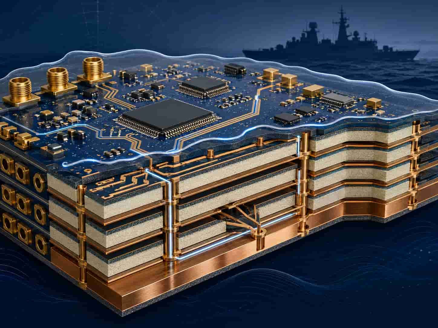
Quick Summary
Key point: Naval high frequency PCB uses Rogers RO4350B for L-band and S-band naval surveillance radar, Rogers RO4003C or RO3003 for X-band fire control and navigation radar, and Rogers RT5880 for shipborne EW systems covering 2–18 GHz. The critical additional requirements beyond standard aerospace PCB are salt fog qualification per MIL-STD-810 Method 509.6 (500+ hours), underwater explosion shock per MIL-S-901D, shipboard vibration per MIL-STD-167, and comprehensive conformal coating for maritime corrosion protection. IPC Class 3 is the workmanship baseline.
The most distinctive requirement of naval PCB compared to other defense applications is the underwater explosion (UNDEX) shock requirement. MIL-S-901D Grade A shock testing subjects equipment to simulated near-miss underwater explosion loads that can exceed thousands of g-equivalent shock at the equipment mounting point. The PCB must survive these loads without damage to via barrels, solder joints, or component connections — a requirement that demands copper-filled vias, careful component mounting, and potting or conformal coating for protection.
Naval Electronics Subsystems and High Frequency PCB Requirements
A modern warship carries multiple radar, sonar, EW, and communication systems, each with different frequency bands and PCB requirements. Understanding the specific system drives correct Rogers material selection and environmental qualification scope.
Naval Surveillance and Search Radar
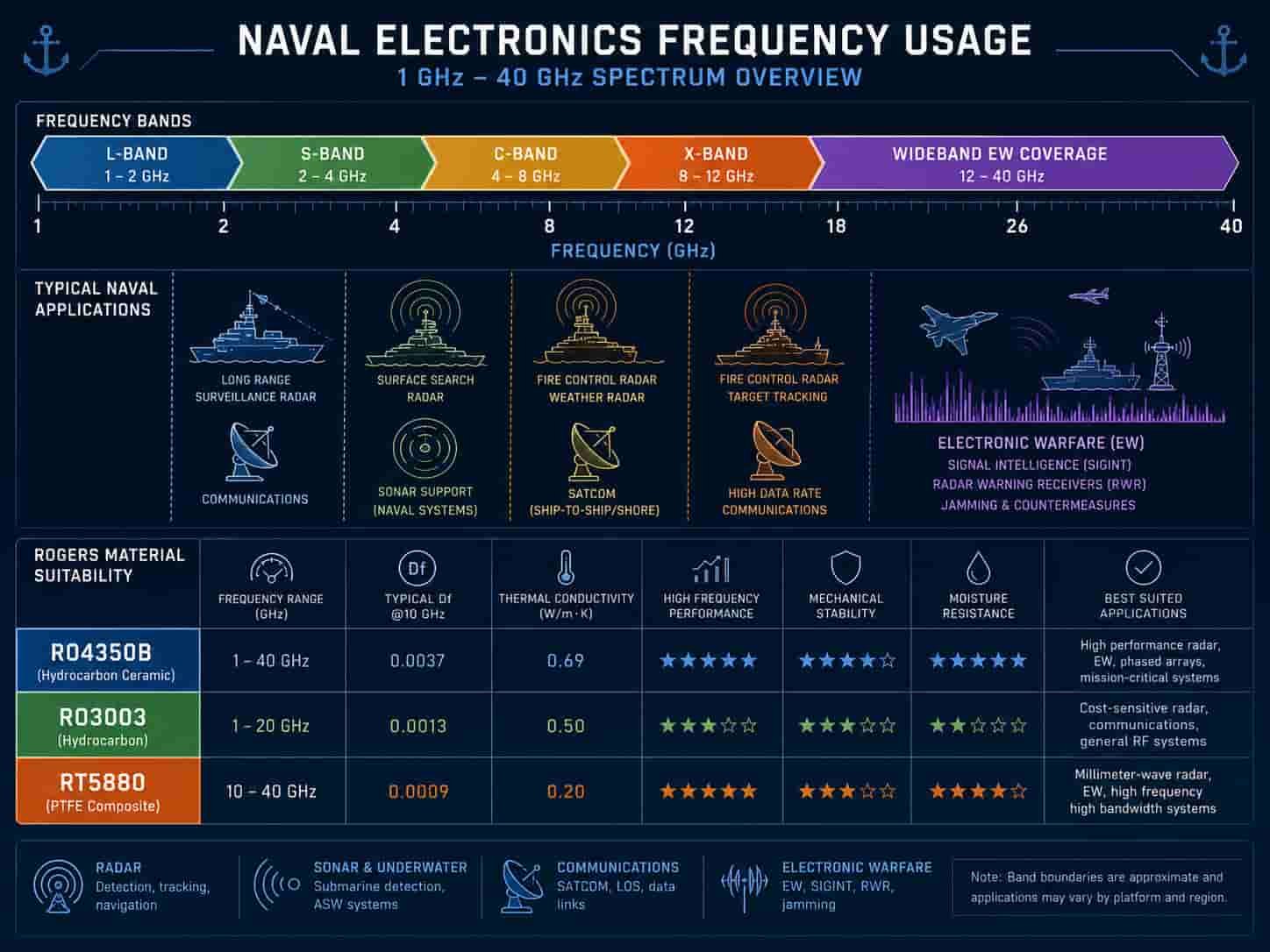
Naval surveillance radar provides long-range detection of airborne, surface, and periscope-depth submarine targets. L-band and S-band are the primary bands for long-range naval surveillance, providing the range and weather penetration needed for fleet air defense and surface search.
- Long-range air search radar (L-band, 1–2 GHz): Rogers RO4350B or FR4 hybrid — lower frequency reduces Rogers material critical area
- Combined air and surface search radar (S-band, 2–4 GHz): Rogers RO4350B — most common for modern naval surveillance arrays
- 3D volume search radar (S-band): phased array — multiple T/R module PCB, Rogers RO4350B
- Surface search and navigation radar (X-band, 8–12 GHz): Rogers RO4003C or RO3003
- All naval radar PCB: MIL-S-901D shock, MIL-STD-167 vibration, salt fog conformal coating
Fire Control and Tracking Radar
Naval fire control radar provides precision tracking of air and surface targets for weapon system guidance. X-band is the dominant frequency for naval fire control, providing the angular resolution and range accuracy needed for missile and gun fire control.
- Naval fire control radar (X-band, 8–12 GHz): Rogers RO4003C — low Df for long feed networks on large phased array
- Precision tracking radar (X-band): Rogers RO3003 — lowest loss for critical fire control accuracy
- CIWS targeting radar (Ka-band, 26.5–40 GHz): Rogers RO3003 — high resolution for close-in engagement
- Phase matching: critical for fire control phased arrays — tight Dk tolerance required
Shipborne Electronic Warfare
Shipborne EW systems detect, classify, and counter radar and communication threats. They require the broadest frequency coverage of any naval system — typically 2–18 GHz or wider for comprehensive threat coverage in the maritime electromagnetic environment.
- ESM / RWR (2–18 GHz): Rogers RT5880 — lowest and most stable Dk across full naval EW band
- ECM / jammers: Rogers RT5880 or RO3003 — power handling for jamming transmitters
- Decoy systems: launchers and seeker defeat electronics — system-dependent frequency
- SIGINT receivers: Rogers RT5880 — lowest loss for maximum intercept range
Naval Communication Systems
Shipborne communication includes HF/VHF/UHF radio, satellite communication, and data links. High frequency PCB is required for the RF power amplifier and front-end circuits of these systems.
- UHF tactical radio PA (300–500 MHz): high-Tg FR4 or Rogers RO4350B for PA PCB
- Shipborne SATCOM terminal (Ku-band or Ka-band): Rogers RO3003 for antenna feed network
- Line-of-sight data link (X-band): Rogers RO4003C
- HF (3–30 MHz): standard FR4 adequate — frequency too low for Rogers material advantage
Sonar Systems
Naval sonar uses acoustic transducers rather than RF radiation, but the signal processing electronics — particularly the beamforming, digital signal processing, and control electronics — may include high frequency interfaces. The PCB inside sonar signal processors is not a high frequency RF PCB in the same sense as radar PCB, but it shares the same naval environmental requirements.
- Sonar transducer drive electronics: high-power, lower frequency — not RF PCB
- Sonar signal processor PCB: high-speed digital — high-speed FR4, not Rogers material
- Sonar to system interface: may include RF data links at X-band — Rogers RO4003C
Rogers PCB Material Selection for Naval Electronics
Rogers material selection for naval electronics follows the same frequency-driven logic as ground-based radar but with additional consideration for the maritime environment and the large panel sizes needed for naval phased array radar.
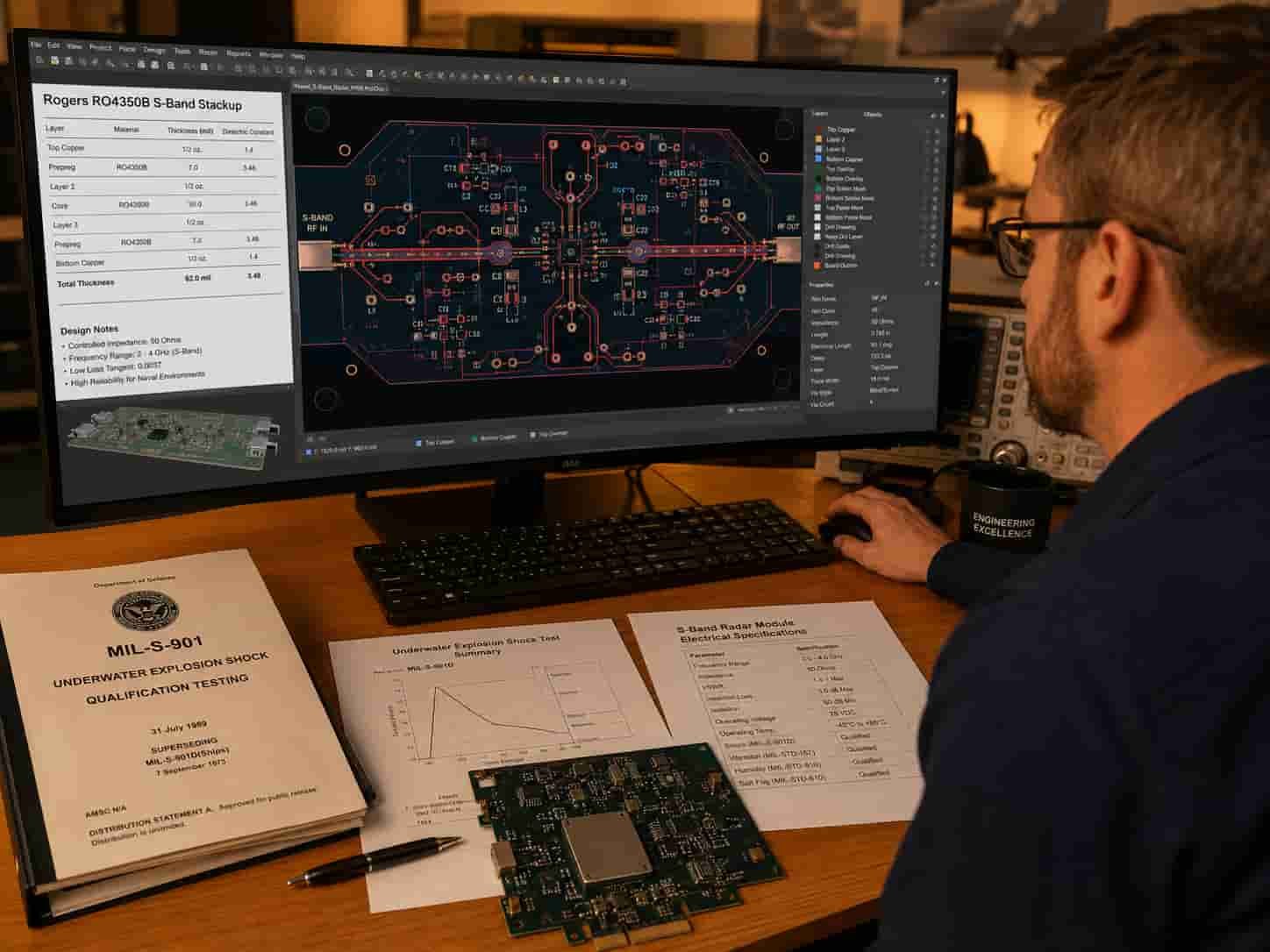
Rogers RO4350B — Naval Surveillance Radar
Rogers RO4350B is the workhorse material for naval surveillance radar PCB at S-band. Its compatibility with standard multilayer lamination, availability in large panels, and cost-effectiveness for the large array PCB of naval surveillance radar make it the practical first choice.
- Dk: 3.48 ±0.05, Df: 0.0037 at 10 GHz — adequate for S-band surveillance arrays
- Tg: >280°C — well above any shipboard operating temperature including engine room environments
- Large panel compatibility: critical for naval array PCB — panels approaching maximum manufacturing size
- Hydrophobicity: lower moisture absorption than FR4 — advantageous in high-humidity naval environment
- Salt fog compatibility: Rogers PTFE-enhanced materials resist salt fog absorption — important for naval use
Rogers RO4003C — Naval Fire Control Radar
Rogers RO4003C (Dk 3.38, Df 0.0027) provides 27% lower Df than RO4350B, which is significant for X-band naval fire control radar where the antenna feed network may span a large phased array aperture.
- Df: 0.0027 vs RO4350B 0.0037 — significant insertion loss advantage at X-band
- Applications: X-band naval fire control radar T/R module PCB, X-band tracking radar
- Compatible with RO4350B hybrid stackup — can use RO4003C on RF layers, RO4350B or FR4 on other layers
Rogers RO3003 — Precision Naval Radar and Ka-Band
Rogers RO3003 is used for the highest precision naval fire control applications and Ka-band CIWS targeting radar where minimum insertion loss and maximum Dk stability over the wide shipboard temperature range are required.
- Dk: 3.0 ±0.04, Df: 0.0010 — lowest loss of common naval radar materials
- x-y CTE: 17 ppm/°C — good dimensional stability for large-format precision tracking array
- Dk temperature coefficient: +13 ppm/°C — most stable Dk over shipboard temperature range
- Applications: Ka-band CIWS PCB, X-band precision fire control with long feed networks
Rogers RT5880 — Shipborne EW
Rogers RT5880 is the standard material for shipborne EW PCB covering the full 2–18 GHz maritime EW band. Its ultra-low Dk and Df, combined with exceptional frequency stability, give naval EW receivers the maximum intercept range and sensitivity.
- Dk: 2.2 ±0.02, Df: 0.0009 — minimum loss across 2–18 GHz EW band
- Hydrophobic PTFE base — excellent moisture resistance in high-humidity maritime environment
- Applications: ESM, ECM, RWR, SIGINT receivers aboard warships
Salt Fog and Corrosion Protection for Naval High Frequency PCB
Salt fog is the defining environmental challenge of naval electronics. Salt-laden air penetrates equipment enclosures, deposits on PCB surfaces, and — in the presence of moisture — creates electrolytic conditions that corrode metal surfaces, grow conductive dendrites between conductors, and degrade solder joint integrity. Naval PCB must be protected against salt fog exposure throughout the system service life.
MIL-STD-810 Salt Fog Testing
- Method 509.6: salt fog test — 5% NaCl solution at 35°C, standard exposure 48–96 hours
- Naval programs often specify extended salt fog: 500+ hours for shipboard electronics
- Post-exposure testing: electrical continuity, isolation, and RF performance must meet specification after salt fog
- IPC Class 3 boards must maintain electrical isolation between conductors after salt fog exposure
- Rogers PTFE materials: hydrophobic surface — naturally more resistant to salt fog absorption than FR4
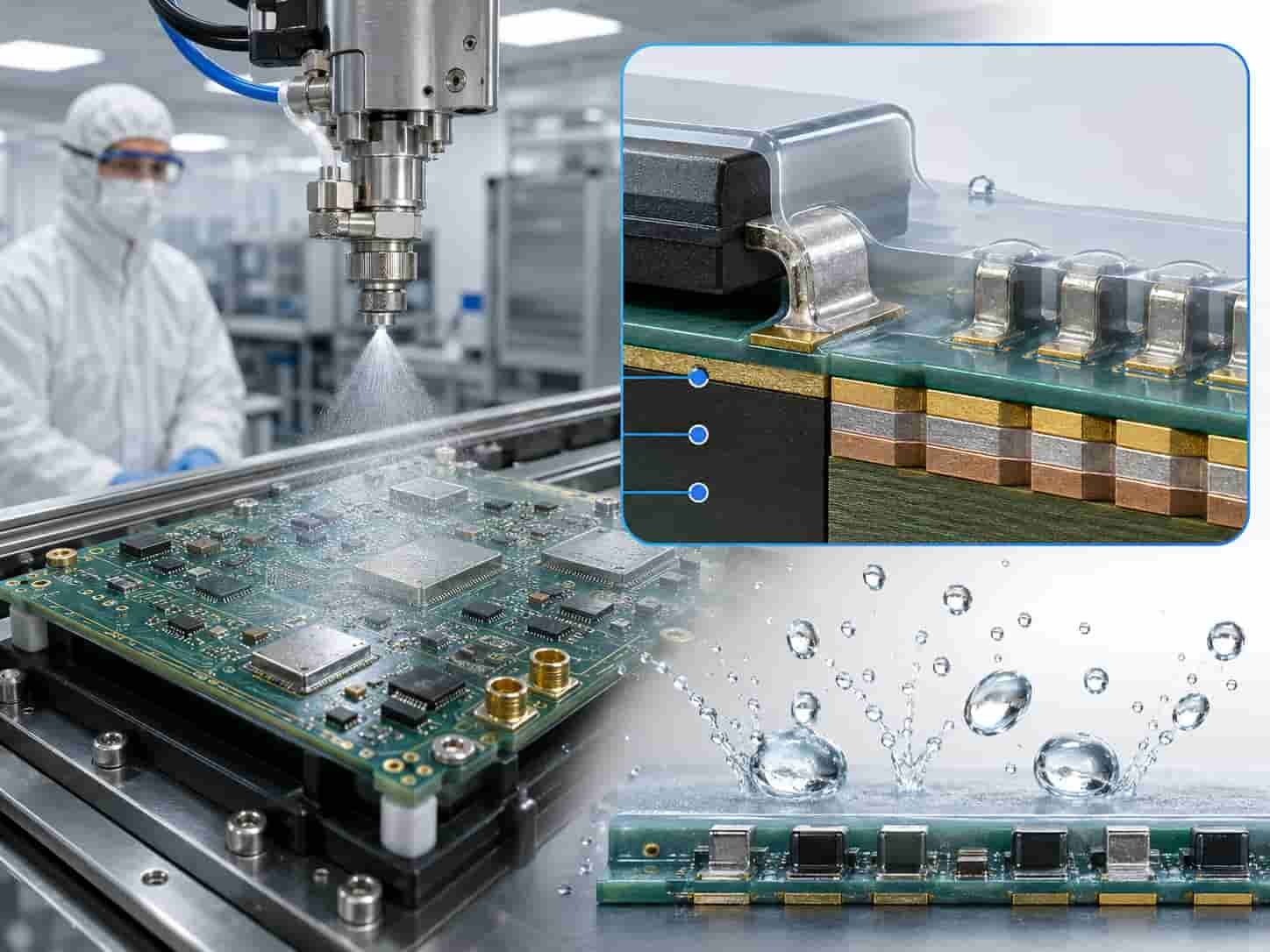
Conformal Coating for Naval PCB
Conformal coating is mandatory for all shipborne electronics PCB. The coating must provide reliable salt fog and humidity protection for the full ship service life — up to 30 years in maritime service.
- Acrylic coating: widely used for naval electronics — good humidity and salt fog protection, reworkable for maintenance
- Polyurethane coating: better chemical resistance than acrylic — used in areas with fuel or lubricant exposure
- Silicone coating: -65°C to +200°C — for high-temperature shipboard locations near machinery
- Epoxy coating: very hard, impermeable — best for highest salt fog resistance, but not reworkable
- Parylene: conformal deposition, pinhole-free — highest reliability for critical naval PCB
- Coating thickness: typically 25–75 µm for acrylic and polyurethane — must cover all conductor surfaces
- Coverage inspection: UV fluorescent inspection of coating — no bare areas permitted
Surface Finish Corrosion Resistance
In the marine environment, surface finish selection affects long-term corrosion resistance of exposed PCB pads and solder joints. ENIG and ENEPIG are the preferred finishes for naval high frequency PCB because their gold outer surface is resistant to salt fog corrosion and maintains solderability for maintenance re-soldering.
- ENIG: gold surface resists salt fog corrosion — preferred for naval RF pads
- ENEPIG: eliminates black pad risk — preferred for high-reliability naval programs and wire-bonded components
- Immersion silver: tarnishes in salt-laden air — not recommended for naval PCB unless immediately assembled and conformal coated
- OSP: minimal corrosion protection — not suitable for naval applications
For surface finish comparison, see ENIG vs ENEPIG vs Immersion Silver for High Frequency PCB.
MIL-S-901D Underwater Explosion Shock Qualification
The most distinctive and demanding environmental requirement unique to naval electronics is the underwater explosion (UNDEX) shock test defined in MIL-S-901D. This test simulates the shock loads experienced by ship equipment when an underwater explosion occurs near the vessel — a scenario that naval equipment must survive without losing function.
MIL-S-901D Shock Classification
- Grade A: equipment must function during and after shock — no interruption of operation
- Grade B: equipment must function after shock — brief interruption acceptable
- Lightweight equipment (≤ 227 kg): tested on lightweight shock machine (LWSM)
- Mediumweight equipment (227–1814 kg): tested on mediumweight shock machine (MWSM)
- Heavyweight equipment (> 1814 kg): barge float shock test or analysis
- Shock severity: peak acceleration at equipment mounting point can exceed 1000 g-equivalent for lightweight class
PCB Design for UNDEX Shock Survival
Surviving MIL-S-901D Grade A shock requires PCB design practices that go beyond standard IPC Class 3 requirements. The PCB must maintain electrical continuity through the shock pulse without any disconnection of via barrels, component leads, or connector contacts.
- Copper-filled vias: required for all through-hole vias — eliminates void that becomes fatigue initiation site
- Via copper plating: 30 µm or above for shock-critical naval PCB — above IPC Class 3 minimum
- Component restraint: heavy components (transformers, connectors, heat sinks) require additional mechanical restraint — staking, potting, or brackets
- Board mounting: PCB must be mounted to chassis with appropriate shock isolators or rigid retention — no resonance within shock frequency range
- Solder joint design: avoid large leadless components without underfill — brittle solder joints are shock failure initiation points
- Potting: critical PCB sections may be fully potted in epoxy for maximum shock protection — at the expense of repairability
MIL-STD-167 Shipboard Vibration
In addition to shock, naval PCB must survive continuous vibration from ship propulsion machinery, generators, and other mechanical equipment. MIL-STD-167 Type I defines vibration requirements for shipboard equipment.
- MIL-STD-167 Type I: 4–33 Hz sinusoidal vibration — main propulsion frequency range
- MIL-STD-167 Type II: 4–50 Hz or broader for equipment near engines or machinery
- PCB natural frequency: should be above 33 Hz to avoid resonance with propulsion vibration
- Heavy component restraint: same requirements as for shock — staking or potting for heavy components
- Conformal coating: retains component solder joints under continuous vibration
IPC Class 3 and Naval Quality Requirements
IPC Class 3 is the workmanship baseline for all naval high frequency PCB. The combination of 25–30 year service life, salt fog exposure, UNDEX shock, and continuous vibration makes Class 3 the minimum acceptable standard — and many naval programs impose requirements above Class 3.
- PTH copper plating: 25 µm average minimum per Class 3 — many naval programs specify 30 µm for UNDEX shock survival
- No annular ring breakout: ensures reliable via connections through repeated thermal cycling and shock
- Copper-filled vias: strongly recommended for all naval PCB — required for UNDEX Grade A applications
- 100% electrical test: every board tested before installation
- Microsection FAI: required — periodic sampling during production
- Salt fog post-test electrical: boards tested for isolation degradation after salt fog qualification
- Conformal coating inspection: UV fluorescent inspection — 100% coverage verification
- Traceability: material certificates, process records, board serialization — retained for ship service life (25–30 years)
- MIL-PRF-31032: US Navy PCB specification for naval programs
For IPC Class 3 requirements, see IPC Class 3 High Frequency PCB: What It Means for Aerospace and Defense Applications. For aerospace and defense material requirements, see High Frequency PCB for Aerospace and Defense: Material, Reliability and Manufacturing Requirements.
EMC Requirements for Naval Electronics — MIL-STD-461
Shipborne electronics must comply with MIL-STD-461 EMC requirements to prevent interference between the many electronic systems operating simultaneously aboard a warship. The dense electromagnetic environment of a warship — with radar, EW, communication, and navigation systems all operating at once — makes EMC control critical for system performance.
- RE102: radiated emissions — naval radar and EW transmitters must not interfere with ship navigation and communication
- RS103: radiated susceptibility — PCB must function under strong radar illumination from own-ship radar
- CS101/CS114: conducted susceptibility — ship power supply noise rejection
- CS116: damped sinusoidal transients — EMP-like conducted transients from ship power switching
- PCB ground plane: solid, continuous ground plane essential for both RF performance and EMC
- Shield enclosures: naval EW and radar PCB often housed in fully shielded chassis — PCB ground must bond reliably to chassis
Information Needed for Naval High Frequency PCB Quotation
To review feasibility and provide an accurate quotation for naval high frequency PCB, the following information should be prepared:
- Gerber files (all layers) and NC drill files
- Complete PCB stackup with Rogers material grade, layer sequence, and copper weight
- Naval system type — surveillance radar, fire control, EW, sonar, communication
- Operating frequency band
- PCB dimensions — panel size and finished board size
- Layer count and board thickness
- Via structure — through-hole, blind, buried, copper-filled via requirement
- Controlled impedance requirements
- MIL-S-901D shock Grade and class requirement
- MIL-STD-167 vibration category
- Salt fog test duration — hours per MIL-STD-810 Method 509.6
- Conformal coating type, thickness, and coverage requirement
- IPC Class 3 and any above-Class-3 requirements
- Surface finish — ENIG, ENEPIG, or other
- Traceability and record retention requirements — ship service life
- Applicable standards — MIL-PRF-31032, MIL-STD-810, MIL-STD-167, MIL-STD-461
- Quantity — prototype, qualification, or production
For a complete file checklist, see What Files Are Needed for a High Frequency PCB Quotation?. For radar system PCB requirements, see High Frequency PCB for Radar Systems: EW, AESA and Ground-Based Radar.
Conclusion
Naval and shipborne high frequency PCB faces the most comprehensive combination of environmental challenges in defense electronics — salt fog, high humidity, UNDEX shock, continuous vibration, and long service life — on top of the standard aerospace requirements of wide temperature range, IPC Class 3, and full material traceability. Rogers RO4350B covers S-band naval surveillance radar, Rogers RO4003C and RO3003 serve X-band fire control and tracking radar, and Rogers RT5880 provides the wide-band low-loss performance required for shipborne EW systems.
Salt fog conformal coating, MIL-S-901D UNDEX shock qualification with copper-filled vias, MIL-STD-167 vibration compliance, and 25–30 year record retention are the naval-specific requirements that distinguish shipborne high frequency PCB from other defense applications. Early engagement with a manufacturer experienced in naval PCB environmental requirements reduces qualification risk and supports the long program timelines typical of naval platform development and production.