Rogers RO4003C sits between Rogers RO4350B and Rogers RO3003 in the high frequency PCB material hierarchy. Its Df of 0.0027 is 27% lower than RO4350B (0.0037) and 2.7× higher than RO3003 (0.0010). Like RO4350B, RO4003C is a hydrocarbon ceramic material that processes on FR4-compatible equipment — no plasma activation, no PTFE-specific drill parameters, same Rogers RO4450F bonding film. This combination of improved RF performance with FR4-compatible manufacturing makes RO4003C the correct choice for X-band designs where RO4350B’s Df is marginally insufficient and full PTFE process is not warranted.
As a direct Rogers PCB factory with RO4003C in production inventory, we build X-band and Ku-band PCB on RO4003C in regular production. This guide covers when RO4003C is the right choice and how to specify it correctly.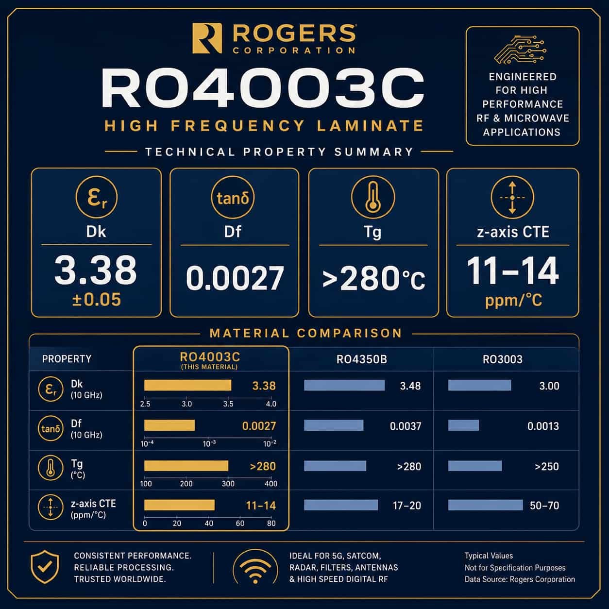
Quick Summary
Key point: Rogers RO4003C (Dk 3.38 ±0.05, Df 0.0027, Tg >280°C) is a hydrocarbon ceramic material with FR4-compatible processing — same equipment as RO4350B, same Rogers RO4450F bonding film, same 3-cycle lamination limit. It costs approximately 20–35% more than RO4350B. The decision to use RO4003C over RO4350B is purely about insertion loss budget: if your longest RF path at X-band or Ku-band produces more loss with RO4350B than your system link budget allows, upgrade to RO4003C. If RO4350B is within budget, there is no performance reason to pay for RO4003C.
Rogers RO4003C Material Properties
Dielectric Constant (Dk)
- Nominal Dk: 3.38 at 10 GHz — lower than RO4350B (3.48) by 0.10
- Dk tolerance: ±0.05 — same as RO4350B
- Dk temperature coefficient: +50 ppm/°C — same as RO4350B
- Practical effect: lower Dk than RO4350B means slightly wider 50Ω traces on RO4003C for same substrate thickness
Dissipation Factor (Df)
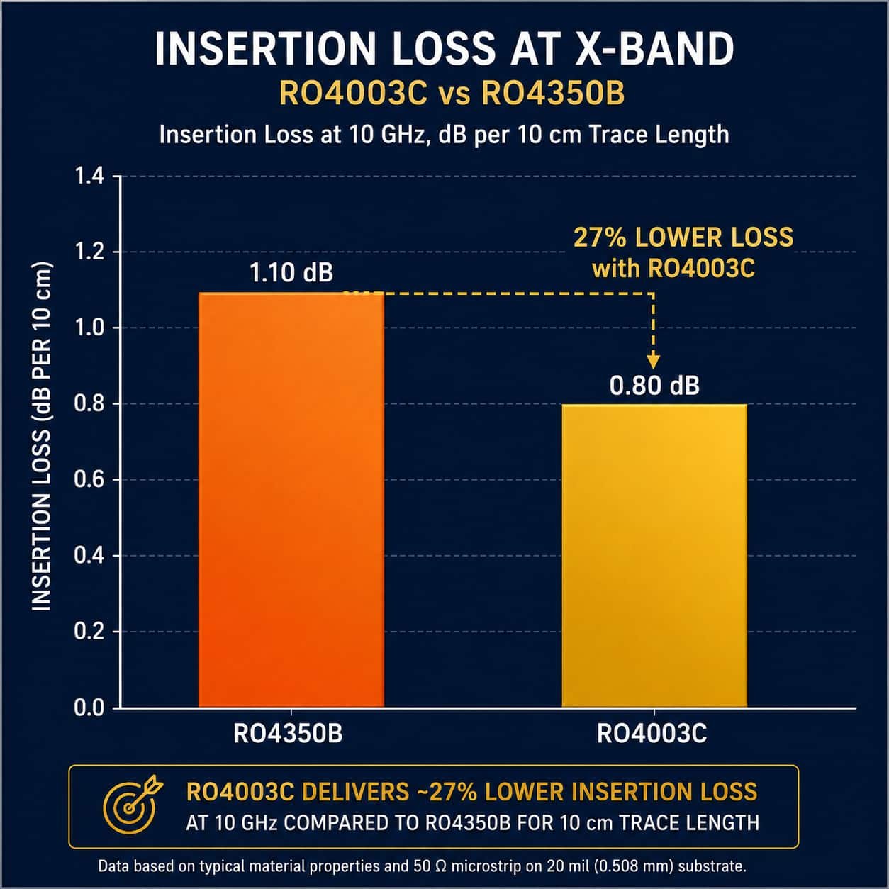
- Df at 10 GHz: 0.0027 — 27% lower than Rogers RO4350B (0.0037)
- Df at 2.4 GHz: approximately 0.0023
- Df at 24 GHz: approximately 0.0029
- Insertion loss advantage over RO4350B at 10 GHz: approximately 0.07 dB/cm
- Over a 150mm RF path at 10 GHz: RO4003C saves approximately 1.0 dB compared to RO4350B
- Compared to RO3003: RO4003C Df is 2.7× higher — but RO4003C does not require PTFE process
z-axis CTE — Key Advantage Over RO4350B
- z-axis CTE: 11–14 ppm/°C — significantly lower than RO4350B (32–46 ppm/°C)
- This is the best z-axis CTE of any standard Rogers hydrocarbon material
- Practical benefit: better via fatigue resistance under thermal cycling than RO4350B
- For designs with many vias in a wide temperature cycling range, RO4003C’s lower z-axis CTE provides better long-term reliability than RO4350B — without requiring PTFE process
Other Key Properties
- Tg: greater than 280°C — same as RO4350B, far above any operating temperature
- Thermal conductivity: 0.71 W/m·K — slightly better than RO4350B (0.69 W/m·K)
- Moisture absorption: 0.04% — lower than RO4350B (0.06%)
- Processing: FR4-compatible — no plasma activation, no PTFE-specific parameters
- Maximum lamination cycles: 3 — same as RO4350B
- Bonding film: Rogers RO4450F — same as RO4350B
When to Choose RO4003C Over RO4350B
The decision between RO4003C and RO4350B is almost always driven by a single calculation: insertion loss over the longest RF path in the design. The following guidance covers the most common decision scenarios.
Calculate the Insertion Loss Difference First
The Df difference between RO4003C (0.0027) and RO4350B (0.0037) produces a consistent insertion loss advantage that scales with frequency and trace length. Use this as a first-pass guide:
- At 10 GHz: RO4003C saves approximately 0.07 dB/cm over RO4350B
- At 10 GHz, 100mm trace: approximately 0.7 dB saving
- At 10 GHz, 200mm trace: approximately 1.4 dB saving
- At 15 GHz: approximately 0.09 dB/cm saving
- At 15 GHz, 100mm trace: approximately 0.9 dB saving
Decision rule: If the insertion loss saving from RO4003C at your operating frequency and trace length is greater than approximately 0.5 dB and that 0.5 dB exceeds your system margin, upgrade to RO4003C. If the saving is less than 0.5 dB or your system has adequate margin with RO4350B, stay with RO4350B and save the 20–35% material cost premium.
X-Band Fire Control Radar with Long Feed Networks
X-band (8–12 GHz) fire control and airborne fire control radar with feed networks longer than 100–150mm are the primary application where RO4003C provides a meaningful advantage over RO4350B. A phased array radar with a 200mm feed network at 10 GHz sees approximately 1.4 dB less insertion loss with RO4003C — in a low-noise receiver system, this improves the noise figure by 1.4 dB.
- Short feed networks (below 100mm at X-band): RO4350B is adequate — cost saving justifies it
- Long feed networks (150mm+ at X-band): RO4003C insertion loss advantage is meaningful
- Phased array with many elements: total feed length may be much longer — evaluate total path
Ku-Band VSAT and Satellite Terminal
Ku-band designs (10.7–14.5 GHz) are at the upper end of the frequency range where RO4003C provides useful advantage over RO4350B. At Ku-band, even moderate feed network lengths produce enough insertion loss with RO4350B to warrant upgrading to RO4003C.
- Ku-band VSAT downlink (10.7–12.75 GHz): RO4003C standard choice for the RF front-end
- Ku-band uplink (13.75–14.5 GHz): RO4003C — lower Df keeps feed loss within link budget
- For very compact Ku-band designs with short traces: RO4350B may be adequate — calculate first
High-Power Amplifier PCB
GaN and GaAs high-power amplifier PCB at X-band and Ku-band benefit from RO4003C’s lower Df for two reasons: less insertion loss in the output matching network means more power reaches the antenna, and lower Df means less dielectric heating at high power levels.
- X-band GaN PA output matching network: RO4003C 0.508mm
- Ku-band traveling wave tube amplifier (TWTA) driver: RO4003C
- Output power above 50W: thermal conductivity matters — RO4003C (0.71 W/m·K) vs RO4350B (0.69 W/m·K)
When RO4003C Is Not Sufficient — Upgrade to RO3003
For applications where even RO4003C’s Df of 0.0027 exceeds the insertion loss budget, Rogers RO3003 (Df 0.0010, PTFE process) is required. The crossover point is approximately:
- Ka-band (above 26.5 GHz): RO3003 required — RO4003C Df too high
- 77 GHz: RO3003 required — RO4003C completely inadequate
- X-band designs where even 0.5 dB improvement from RO4003C is insufficient: evaluate RO3003
- Note: upgrading from RO4003C to RO3003 requires changing to PTFE manufacturing process — significant process change
For Ka-band PCB on Rogers RO3003, see Rogers RO3003 PCB: Ka-Band, 77GHz and Defense Applications Guide. For material selection overview, see Rogers PCB Material Selection Guide.
Rogers RO4003C Applications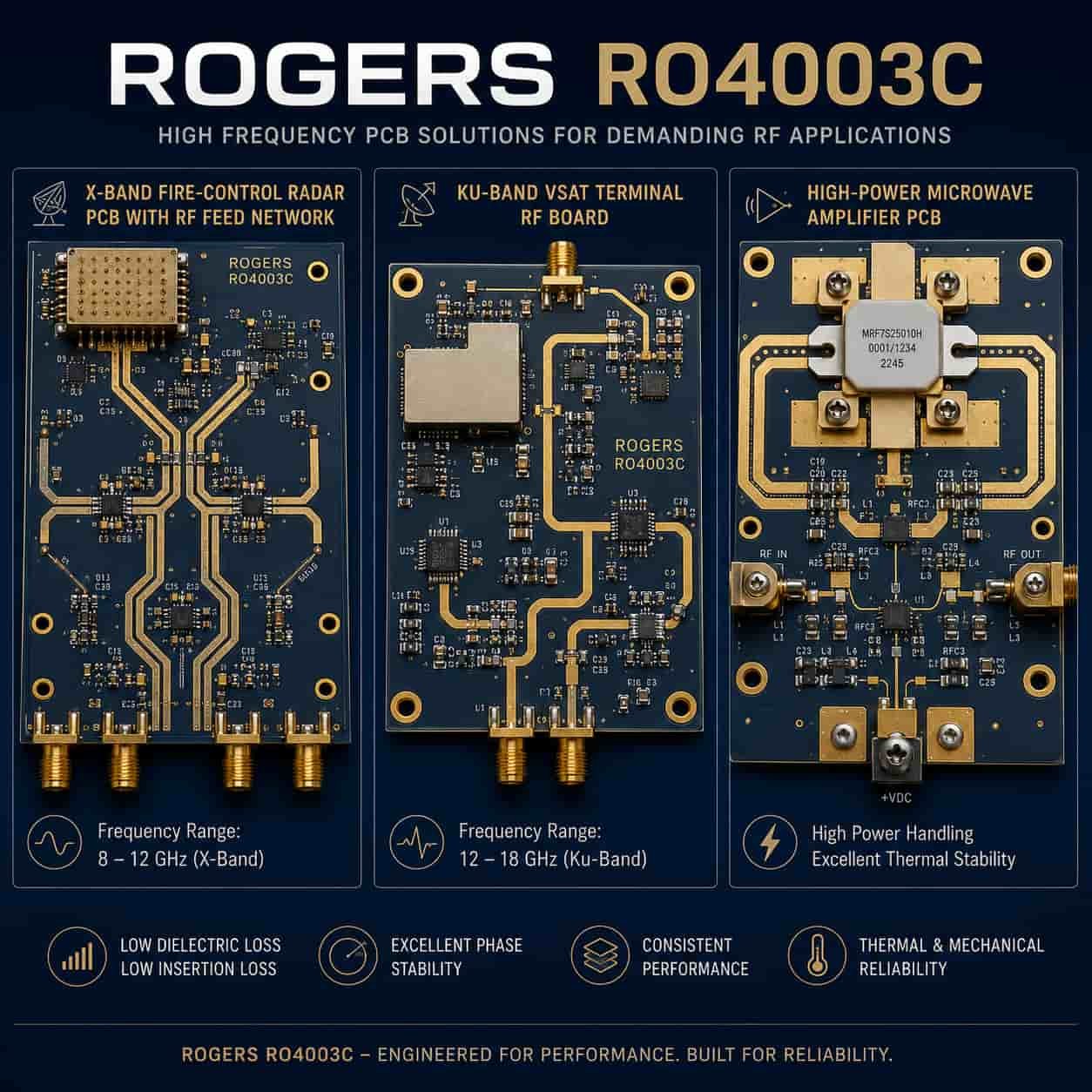
X-Band Airborne Fire Control Radar
- Frequency: 8.5–10.5 GHz
- Material: Rogers RO4003C — lower Df than RO4350B for improved SNR in airborne radar
- Stackup: RO4003C on RF signal layers, FR4 or RO4003C on other layers
- Quality: IPC Class 3 for airborne applications
- Surface finish: ENIG or ENEPIG
See: High Frequency PCB for Aerospace and Defense
Ku-Band VSAT Ground Terminal
- Frequency: 10.7–14.5 GHz
- Material: Rogers RO4003C — standard choice for VSAT RF front-end above 10 GHz
- Typical PCB: LNB input filter, frequency converter, power amplifier driver
- Quality: IPC Class 2 for commercial VSAT
See: High Frequency PCB for Satellite Communication
X-Band Ship-Based Radar
- Frequency: 9.0–9.5 GHz (maritime navigation and fire control)
- Material: Rogers RO4003C for receiver front-end and antenna feed
- Environment: salt air — moisture absorption of RO4003C (0.04%) lower than RO4350B (0.06%)
See: High Frequency PCB for Naval and Shipborne Electronics
Point-to-Point Microwave Link (6–11 GHz)
- Frequency: 6–11 GHz licensed bands
- Material: Rogers RO4003C — lower Df than RO4350B for link budget optimization
- Application: outdoor unit (ODU) RF front-end PCB
- Quality: IPC Class 2 commercial
Radar Altimeter
- Frequency: 4.2–4.4 GHz (civil aviation) or 13.25–13.4 GHz (Ku-band altimeter)
- Material: Rogers RO4003C for Ku-band altimeter — RO4350B adequate at 4.3 GHz
- Quality: IPC Class 3 — aviation safety-critical
Impedance Calculation for Rogers RO4003C
Rogers RO4003C has a slightly lower Dk than RO4350B (3.38 vs 3.48), which means 50Ω trace widths are slightly different. The difference is small — approximately 0.02–0.05mm wider trace on RO4003C than on RO4350B for the same substrate thickness.
50Ω Microstrip Trace Width on Rogers RO4003C
- RO4003C 0.203 mm, 1 oz: 50Ω trace ≈ 0.39 mm (15 mil)
- RO4003C 0.305 mm, 1 oz: 50Ω trace ≈ 0.60 mm (24 mil)
- RO4003C 0.406 mm, 1 oz: 50Ω trace ≈ 0.82 mm (32 mil)
- RO4003C 0.508 mm, 1 oz: 50Ω trace ≈ 1.05 mm (41 mil)
- RO4003C 0.813 mm, 1 oz: 50Ω trace ≈ 1.71 mm (67 mil)
- RO4003C 1.524 mm, 1 oz: 50Ω trace ≈ 3.30 mm (130 mil)
Manufacturing note: These values use nominal Dk 3.38. Our factory recalculates using confirmed production Dk from the Rogers material certificate for the assigned lot. RO4003C is available in thinner substrates (0.203mm) than RO4350B’s standard range starts at 0.101mm — useful for compact X-band and Ku-band designs requiring thin substrates.
Rogers RO4003C Manufacturing Process
Rogers RO4003C is a hydrocarbon ceramic material — the same material family as RO4350B. Its manufacturing process is identical to RO4350B in all key aspects.
- Process type: FR4-compatible — no plasma activation required
- Drill parameters: standard FR4 parameters — no PTFE-specific requirements
- Bonding film: Rogers RO4450F or RO4450T — same as RO4350B
- Lamination: standard press equipment, Rogers-specified temperature profile
- Maximum press cycles: 3 — same as RO4350B
- Hybrid stackups: RO4003C + FR4, RO4003C + RO4350B, all with Rogers RO4450F bondply
- Impedance: TDR verified every lot, confirmed lot Dk from Rogers certificate
Key advantage: RO4003C’s FR4-compatible process means a factory with proven RO4350B capability can produce RO4003C with no process changes. The only difference is the Rogers material substrate. For buyers, this means RO4003C availability is nearly as wide as RO4350B — unlike PTFE materials that require specialized plasma activation capability.
Rogers RO4003C Standard Thicknesses
- 203 mm — thin substrate for compact X-band designs
- 305 mm
- 406 mm
- 508 mm — most common for X-band PCB
- 813 mm
- 524 mm
Availability note: RO4003C standard thickness range starts at 0.203mm, while RO4350B starts at 0.101mm. For designs requiring substrates thinner than 0.203mm — certain Ka-band transition designs or very compact modules — RO4350B offers thinner options, though at those frequencies RO3003 would typically be the correct specification.
Rogers RO4003C Production at Riching PCB
- RO4003C thicknesses in inventory: 0.203 / 0.305 / 0.406 / 0.508 / 0.813 / 1.524 mm
- Rogers RO4450F bondply in stock for RO4003C hybrid stackups
- FR4-compatible process — same production line as RO4350B
- Controlled impedance: ±10% standard, ±8% advanced — TDR verified every lot
- Impedance calculation: confirmed lot Dk from Rogers material certificate
- Minimum outer layer line width: 2.5 mil advanced, 3 mil standard
- Minimum drill: 0.1 mm advanced, 0.2 mm standard
- Maximum aspect ratio: 14:1 advanced, 10:1 standard
- Maximum lamination cycles: 3
- IPC Class 3: available for aerospace and defense programs
- Rogers-certified material certificates with lot numbers: available for all RO4003C production
What to Specify for Rogers RO4003C PCB Quotation
- Rogers RO4003C — confirm substrate thickness from standard range
- Copper weight per layer
- Complete stackup with layer sequence, material, copper weight, dielectric thickness
- Controlled impedance — target value, tolerance, layer, structure
- Operating frequency — X-band or Ku-band range
- IPC Class — 2 or 3
- Application type — radar, VSAT, amplifier, commercial
- Rogers-certified documentation if required
- Surface finish and quantity
For the complete file checklist, see What Files Are Needed for a High Frequency PCB Quotation?. For full Rogers material selection, see Rogers PCB Material Selection Guide.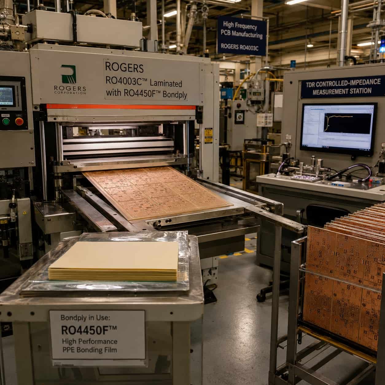
Conclusion
Rogers RO4003C is the correct choice when Rogers RO4350B’s insertion loss at X-band or Ku-band marginally exceeds the system link budget and a full upgrade to PTFE process (RO3003) is not warranted. Its 27% lower Df than RO4350B, best-in-class z-axis CTE among Rogers hydrocarbon materials (11–14 ppm/°C), and FR4-compatible manufacturing make it a low-friction upgrade from RO4350B for X-band fire control radar, Ku-band VSAT, and high-power amplifier PCB.
As a direct Rogers PCB factory with RO4003C in production inventory and the same FR4-compatible process as RO4350B, we build RO4003C PCB with the same lead time and process reliability as RO4350B — no additional process development needed. Submit your X-band or Ku-band design for DFM review and we confirm whether the insertion loss improvement justifies the RO4003C material cost before you commit.