Rogers RO3003 is the standard PCB material for Ka-band applications and 77 GHz automotive radar. Where Rogers RO4350B handles the majority of RF and microwave designs from L-band through X-band, RO3003 takes over at Ka-band — providing the lower Df, more stable Dk over temperature, and tighter dimensional consistency that 26.5–40 GHz circuits require.
As a direct Rogers PCB factory with RO3003 and RO3003G2 in regular production inventory and plasma activation equipment in-house, we build Ka-band PCB, 77 GHz automotive radar boards, and defense AESA PCB on RO3003 every week. This guide covers everything needed to correctly specify, design, and manufacture Rogers RO3003 PCB.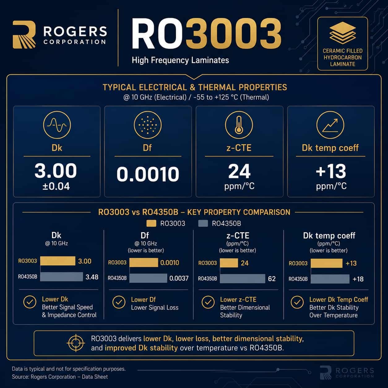
Quick Summary: Rogers RO3003 Key Facts
Key point: Rogers RO3003 (Dk 3.0 ±0.04, Df 0.0010 at 10 GHz, PTFE ceramic) is a PTFE material — it requires plasma or sodium naphthalene hole wall activation before copper plating, PTFE-specific drill parameters, Rogers 2929 bondply for hybrid stackups, and a maximum of 2 lamination press cycles. It is NOT processed on standard FR4-compatible equipment. A factory that processes Rogers RO4350B but not RO3003 does not have the PTFE capability needed for Ka-band PCB. RO3003 Df of 0.0010 is 73% lower than Rogers RO4350B (Df 0.0037), and its Dk temperature coefficient of +13 ppm/°C is 4× more stable than RO4350B (+50 ppm/°C).
Rogers RO3003 Material Properties
Dielectric Constant (Dk)
- Nominal Dk: 3.00 at 10 GHz
- Dk tolerance: ±0.04 — production Dk confirmed from Rogers material certificate lot
- Dk frequency dependence: very stable — minimal variation from 1 GHz to 77 GHz, unlike FR4 and Rogers hydrocarbon materials
- Dk temperature coefficient: +13 ppm/°C — 4× more stable than Rogers RO4350B (+50 ppm/°C)
- Practical significance: at Ka-band, a Dk shift of 1% causes a resonant frequency shift of approximately 250 MHz at 35 GHz — RO3003’s stable Dk keeps antenna resonance consistent over the operating temperature range
- RO3003G2: same nominal Dk 3.0, tighter tolerance ±0.03 — preferred for high-volume 77 GHz production requiring consistent lot-to-lot antenna resonance
Dissipation Factor (Df)
- Df at 10 GHz: 0.0010 — 73% lower than Rogers RO4350B (0.0037)
- Df at 35 GHz: approximately 0.0013 — slight increase at higher Ka-band frequencies
- Df at 77 GHz: approximately 0.0015 — still significantly lower than RO4350B
- Insertion loss at 35 GHz: approximately 0.18 dB/cm on 0.254mm substrate with 0.5 oz copper microstrip
- Comparison: Rogers RO4350B at 35 GHz — approximately 0.50 dB/cm — nearly 3× higher insertion loss
Thermal and Mechanical Properties
- z-axis CTE: 24 ppm/°C — significantly better than Rogers RT5880 (237 ppm/°C), important for via fatigue resistance
- x-y CTE: 17 ppm/°C — close to copper (17 ppm/°C), minimal dimensional change under thermal cycling
- Tg: greater than 500°C — PTFE has no practical glass transition, far above any solder reflow temperature
- Thermal conductivity: 0.50 W/m·K — higher than RT5880 (0.20 W/m·K)
- Moisture absorption: 0.04% — very low, excellent Dk stability in humid environments
Why z-axis CTE matters for Ka-band: Rogers RT5880 has a z-axis CTE of 237 ppm/°C — much higher than RO3003’s 24 ppm/°C. In a multilayer PCB with many vias, high z-axis CTE causes via fatigue under thermal cycling. For Ka-band designs requiring high via density (such as AESA phased arrays with many via-fence isolation structures), RO3003’s lower z-axis CTE provides significantly better via reliability over the program lifetime.
Why RO3003 Is Required at Ka-Band
The decision to specify Rogers RO3003 instead of RO4350B at Ka-band is driven by two factors working together: insertion loss budget and Dk temperature stability.
Insertion Loss at Ka-Band
At 35 GHz, Rogers RO4350B produces approximately 0.50 dB/cm of insertion loss on a 0.254mm substrate — nearly 3× the insertion loss of RO3003 (0.18 dB/cm). For a Ka-band feed network with 50mm of microstrip trace, this difference is approximately 1.6 dB. In a satellite terminal or missile seeker receiver, 1.6 dB of additional feed loss adds directly to the system noise figure. For most Ka-band applications, this difference exceeds the design’s insertion loss budget.
Dk Temperature Stability
Rogers RO3003’s Dk temperature coefficient of +13 ppm/°C means the Dk changes by only 0.0039 over a 300°C temperature range. Rogers RO4350B’s +50 ppm/°C coefficient means a 0.015 change over the same range. At 35 GHz, the RO4350B Dk shift produces a resonant frequency change of approximately 150 MHz per 100°C — enough to pull a narrow-band antenna out of its operating band over an aerospace temperature range (-55°C to +125°C).
Rogers RO3003 Standard Thicknesses
- 127 mm: used for 39 GHz and above where smallest antenna element dimensions are required
- 254 mm: standard for Ka-band (26.5–40 GHz) and 77 GHz automotive radar — most widely used RO3003 thickness
- 508 mm: used where board rigidity is needed or trace width needs to be wider for manufacturability
- 762 mm: less common for Ka-band, used for specific mechanical requirements
- 524 mm: used as a mechanical substrate or for lower-frequency designs requiring RO3003 Dk stability
Design guidance: For most Ka-band designs, 0.254mm is the correct starting point. It provides manageable 50Ω trace widths (approximately 0.22mm at Ka-band) while maintaining adequate mechanical rigidity. For 77 GHz automotive radar, 0.254mm or 0.127mm depending on the antenna element dimension constraint.
Impedance Calculation for Rogers RO3003
Rogers RO3003 has a lower Dk than RO4350B (3.0 vs 3.48), which means the 50Ω trace width on RO3003 is slightly narrower than on RO4350B for the same substrate thickness. At Ka-band frequencies, trace widths approach the minimum line width limit of standard manufacturing process.
50Ω Microstrip Trace Width on Rogers RO3003
Calculated using nominal Dk 3.0 with 0.5 oz (17.5 µm) finished copper — standard for Ka-band designs where thin copper minimizes conductor loss:
- RO3003 0.127 mm substrate: 50Ω trace width ≈ 0.22 mm (8.7 mil)
- RO3003 0.254 mm substrate: 50Ω trace width ≈ 0.30 mm (11.8 mil) with 0.5 oz copper
- RO3003 0.254 mm substrate: 50Ω trace width ≈ 0.22 mm (8.7 mil) with 1 oz copper
- RO3003 0.508 mm substrate: 50Ω trace width ≈ 0.56 mm (22 mil) with 0.5 oz copper
Manufacturing note: At Ka-band on 0.254mm substrate with 0.5 oz copper, the 50Ω trace width of 0.30mm (11.8 mil) is well within standard manufacturing capability. At 39 GHz on 0.127mm substrate, the trace narrows to approximately 0.22mm (8.7 mil) — still within standard capability but approaching the range where our factory’s confirmed 2.5 mil advanced line width limit becomes relevant for complex circuits. We recalculate all Ka-band impedance using confirmed production Dk from the Rogers material certificate before every order.
Rogers RO3003 Manufacturing Process
Rogers RO3003 is a PTFE material. Its manufacturing process differs from Rogers RO4350B in three critical areas: hole wall activation, drilling parameters, and bonding film.
Hole Wall Activation — Mandatory
PTFE is chemically inert. Electroless copper does not bond to PTFE hole walls without prior surface activation. This is the most critical process step for RO3003 PCB reliability.
- Our method: plasma activation — RF plasma etches the PTFE hole wall surface, creating polar functional groups that accept copper deposition
- Without activation: the copper deposits but has weak adhesion. The board passes initial electrical test and fails when thermally cycled.
- We perform plasma activation on every RO3003 order — without exception
- Verification question: ask any RO3003 PCB supplier ‘what hole wall activation method do you use for RO3003?’ Immediate, specific answer = genuine PTFE capability. Vague answer = risk
Drilling Parameters
- Spindle speed: lower than FR4 and RO4350B — PTFE softens at the drill tip under heat
- Feed rate: lower than FR4 — prevents PTFE deformation and hole wall smearing
- Entry and exit materials: PTFE-specific cover and backer to prevent burring
- At 0.254mm substrate: Ka-band designs typically have via diameters of 0.15–0.3mm — within our standard PTFE drilling capability
Bonding Film for RO3003 Hybrid Stackups
- Required bonding film: Rogers 2929 bondply — NOT Rogers RO4450F, NOT standard FR4 prepreg
- Rogers RO4450F is for RO4350B and RO4003C hybrids — it is NOT compatible with PTFE surfaces
- Standard FR4 prepreg creates an impedance discontinuity at the Rogers-FR4 interface
- Rogers 2929 bondply: in stock at our factory — confirmed before every RO3003 hybrid order
Lamination
- Maximum 2 press cycles — strictly enforced for all PTFE materials including RO3003
- PTFE-specific press temperature and pressure profile
- For RO3003 + FR4 hybrid: 2 cycles maximum — set by the PTFE layer
- Via planning: a 1-stage blind via design uses 2 cycles — at the RO3003 limit. 2-stage blind via requires 3 cycles — not possible with RO3003.
For full PTFE manufacturing process details, see PTFE PCB: Material Properties, Manufacturing Process and Applications. For microwave PCB fabrication process, see Microwave PCB Fabrication: Process, Materials and Manufacturing Requirements.
Rogers RO3003 Applications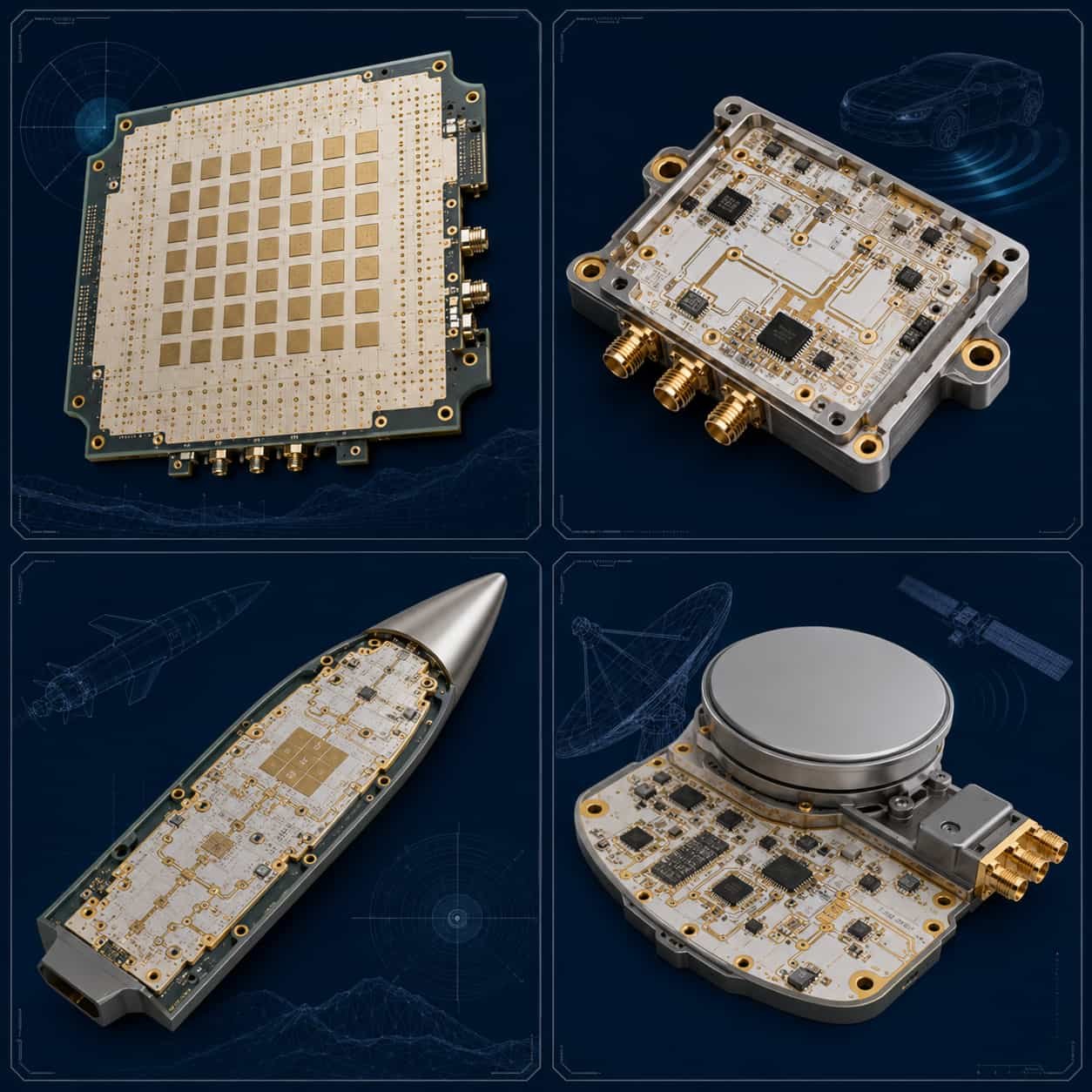
Ka-Band Radar: Missile Seeker and Fire Control
Ka-band (26.5–40 GHz) missile seeker PCB is one of the most demanding RO3003 applications. The seeker antenna must maintain resonance over a wide temperature range (-55°C to +85°C), survive high-g launch vibration, and operate reliably for the missile’s service life. RO3003’s stable Dk over temperature and low z-axis CTE (24 ppm/°C) make it the standard material for this application.
- Substrate thickness: 0.254 mm standard
- Copper weight: 0.5 oz — reduces conductor loss at Ka-band
- Via structure: through-hole plus 1 blind via stage maximum (2 cycle limit)
- Quality standard: IPC Class 3, Rogers-certified material documentation, lot number traceability
- Surface finish: ENIG or ENEPIG for IPC Class 3 defense programs
AESA Phased Array Radar
Active electronically scanned array (AESA) radar PCB for airborne and shipborne radar systems operating at Ka-band. RO3003 is specified for the antenna layer due to its Dk stability and low Df. FR4 or RO4350B is often used for the digital beamforming layers in hybrid stackups to reduce cost.
- Stackup: RO3003 on antenna and RF signal layers, FR4 or RO3003 on other layers
- Bonding film at RO3003-FR4 interface: Rogers 2929 bondply
- Via structure: through-hole vias with careful planning for 2-cycle lamination limit
- Layer count: 6–16 layers typical for AESA feed network
See: High Frequency PCB for Aerospace and Defense
77 GHz Automotive Radar
77 GHz automotive radar for ADAS (Advanced Driver Assistance Systems) is the highest-volume Ka-band application for Rogers RO3003. Every modern vehicle with adaptive cruise control, automatic emergency braking, or blind spot monitoring contains a 77 GHz radar module with RO3003 PCB.
- Standard material: Rogers RO3003 (prototype/low volume) or RO3003G2 (high volume production)
- RO3003G2 advantage: tighter Dk tolerance ±0.03 vs ±0.04 — reduces unit-to-unit antenna resonance variation across production lots
- Substrate thickness: 0.254 mm standard for 77 GHz, 0.127 mm for smallest antenna element designs
- Antenna element size at 77 GHz on 0.254 mm RO3003: approximately 1.1 mm × 1.1 mm
- Manufacturing challenge: 77 GHz trace widths approach 2.5 mil — confirm factory advanced line width capability
See: High Frequency PCB for Automotive Radar and ADAS
Ka-Band Satellite Communication
Ka-band SATCOM terminals (17–20 GHz downlink, 27–30 GHz uplink) and High Throughput Satellite (HTS) systems require RO3003 for the antenna feed network and RF switching PCB.
- Typical frequency: 17.7–20.2 GHz (downlink), 27.5–30.0 GHz (uplink)
- Material: Rogers RO3003 0.254 mm
- Application: patch antenna array, power divider network, RF switch matrix
See: High Frequency PCB for Satellite Communication
Electronic Warfare and SIGINT
EW systems requiring coverage from Ka-band upward — 26.5 GHz and above — specify RO3003 for the Ka-band signal processing stages. For systems covering the wider 2–40 GHz EW band, a hybrid approach is common: Rogers RT5880 on the 2–18 GHz wideband layers and RO3003 on the Ka-band stages.
- Ka-band EW: RO3003 for 26.5–40 GHz stages
- Wideband 2–40 GHz: hybrid RT5880 + RO3003 stackup
See: Rogers PCB for Electronic Warfare Systems
Rogers RO3003 vs RO4350B vs RT5880: When to Use Each
Choose RO3003 When:
- Operating frequency is Ka-band (26.5–40 GHz) or 77 GHz — RO4350B insertion loss is too high at these frequencies
- Dk temperature stability is critical — RO3003 +13 ppm/°C vs RO4350B +50 ppm/°C
- High via density design requires good z-axis CTE — RO3003 24 ppm/°C vs RT5880 237 ppm/°C
- Defense AESA programs specifying Rogers RO3003 on the fabrication drawing
- 77 GHz automotive radar where high-volume consistency requires RO3003G2 Dk ±0.03
Choose RO4350B Instead When:
- Operating frequency is below X-band (12 GHz) — RO4350B Df is adequate and cost is lower
- FR4-compatible process is required — RO4350B does not need plasma activation
- Large-panel production for 5G base station antenna at 3.5 GHz
- Cost-sensitive commercial design where RO3003 Df advantage is within loss budget but not required
Choose RT5880 Instead When:
- Wideband coverage from 2–18 GHz or wider is required — RT5880 has more consistent Dk over this range
- W-band (75–110 GHz) application — RT5880 is the only viable standard material
- Ultra-low loss is the absolute priority and via density is low — RT5880 Df 0.0009 vs RO3003 0.0010
- Note: RT5880’s z-axis CTE of 237 ppm/°C is far worse than RO3003’s 24 ppm/°C — avoid RT5880 for high via density designs
For full Rogers material selection guidance, see Rogers PCB Material Selection Guide.
Rogers RO3003 Production at Riching PCB
- RO3003 thicknesses in inventory: 0.127 mm / 0.254 mm / 0.508 mm / 0.762 mm / 1.524 mm
- RO3003G2: 0.254 mm in stock — for high-volume 77 GHz programs requiring Dk ±0.03
- Rogers 2929 bondply: in stock for RO3003 hybrid stackups
- Hole wall activation: plasma — our standard PTFE process
- Controlled impedance: ±10% standard, ±8% advanced — TDR verified every lot using confirmed lot Dk
- Minimum line width: 2.5 mil advanced, 3 mil standard
- Minimum drill: 0.1 mm advanced, 0.2 mm standard
- Maximum aspect ratio: 14:1 advanced, 10:1 standard
- Maximum lamination cycles: 2 — strictly observed
- IPC Class 3: available — 25 µm average PTH plating, microsection FAI, Rogers material certificates
- Layer count: 2–32 standard, up to 50 advanced
What to Specify for Rogers RO3003 PCB Quotation
- Rogers RO3003 or RO3003G2 — specify which grade
- Substrate thickness — 0.127 mm or 0.254 mm for Ka-band, confirm standard availability
- Copper weight — 0.5 oz or 1 oz per layer
- Complete stackup — every layer with material, thickness, copper weight
- Bonding film — Rogers 2929 bondply for hybrid stackups (factory confirms in stock)
- Controlled impedance — target value, tolerance, layer, trace structure
- Operating frequency — Ka-band range
- Via structure — confirm total lamination cycle count within 2-cycle limit
- IPC Class — 2 or 3
- Application type — commercial, automotive, aerospace, defense
- Rogers-certified documentation requirement if applicable
- Quantity and delivery
For the complete file checklist, see What Files Are Needed for a High Frequency PCB Quotation?.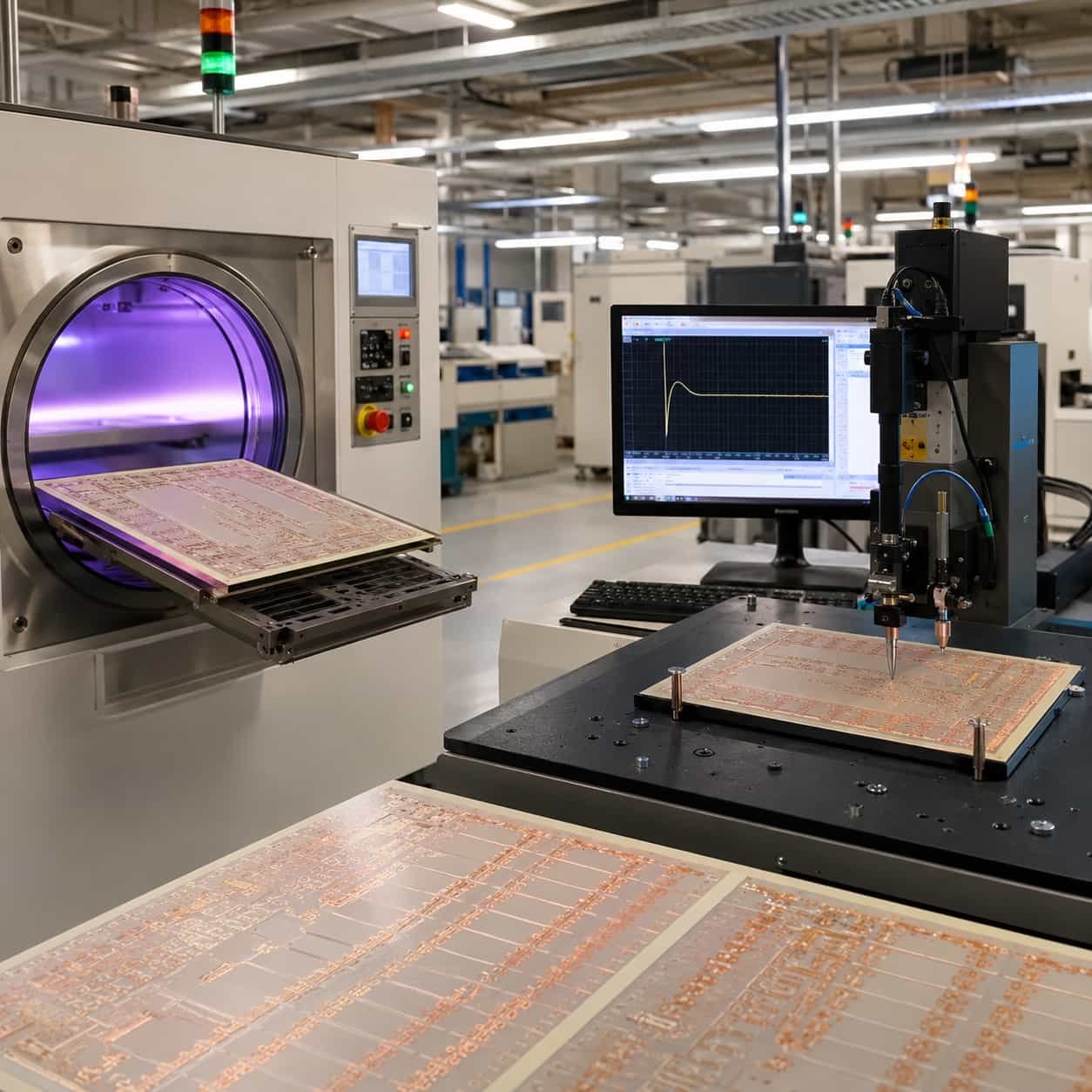
Conclusion
Rogers RO3003 is the standard Ka-band and 77 GHz PCB material because it solves two problems simultaneously: Df of 0.0010 keeps insertion loss within budget at 35–77 GHz, and Dk temperature coefficient of +13 ppm/°C keeps antenna resonance stable over the full aerospace and automotive temperature range. The z-axis CTE of 24 ppm/°C also provides better via fatigue resistance than Rogers RT5880 for high-density Ka-band multilayer designs.
As a direct Rogers PCB factory with RO3003 and RO3003G2 in production inventory, plasma activation in-house, and Rogers 2929 bondply in stock, we review every RO3003 order with our engineering team before production — confirming impedance using lot Dk, PTFE process steps, and bonding film selection before your Ka-band design is committed to production.