
ENIG vs ENEPIG vs Immersion Silver for RF PCB — Which Surface Finish and Why
Surface finish selection for RF PCB is not purely a solderability or cost decision — at high frequency, the finish sits directly in the current path of every microstrip trace and connector pad, and the metal layers involved have measurably different conductivity. This guide compares ENIG, ENEPIG, immersion silver and other common finishes on the parameters that matter for RF PCB: insertion loss contribution, wire bond compatibility, shelf life, and when each is the correct choice.
Home » ENIG vs ENEPIG vs Immersion Silver for RF PCB — Which Surface Finish and Why
Table of Contents
Surface Finish Specifications
| Finish | Nickel Thickness | Gold/Silver Thickness | Key Characteristic |
|---|---|---|---|
| ENIG | 120–300 µin | 1–5 µin gold | Flat, solderable, standard RF choice |
| ENEPIG | 120–300 µin | Pd 1–2 µin (max 20µin), Au 1–5 µin | Palladium barrier — supports wire bonding |
| Immersion Silver | — | 0.15–0.40 µin silver | No nickel — lowest insertion loss |
| Immersion Tin | — | 1.0–1.3 µin tin | Flat, low cost — limited shelf life |
| OSP | — | 0.20–0.60 µm organic | Flattest surface, no metal — shortest shelf life |
The critical structural difference for RF performance is whether the finish includes a nickel layer. ENIG and ENEPIG both use electroless nickel as a barrier layer beneath the precious metal — nickel has significantly lower electrical conductivity than copper or gold. Immersion silver, immersion tin and OSP apply directly onto copper with no nickel barrier, which is why they have measurably lower conductor loss at high frequency.
Insertion Loss Impact by Finish
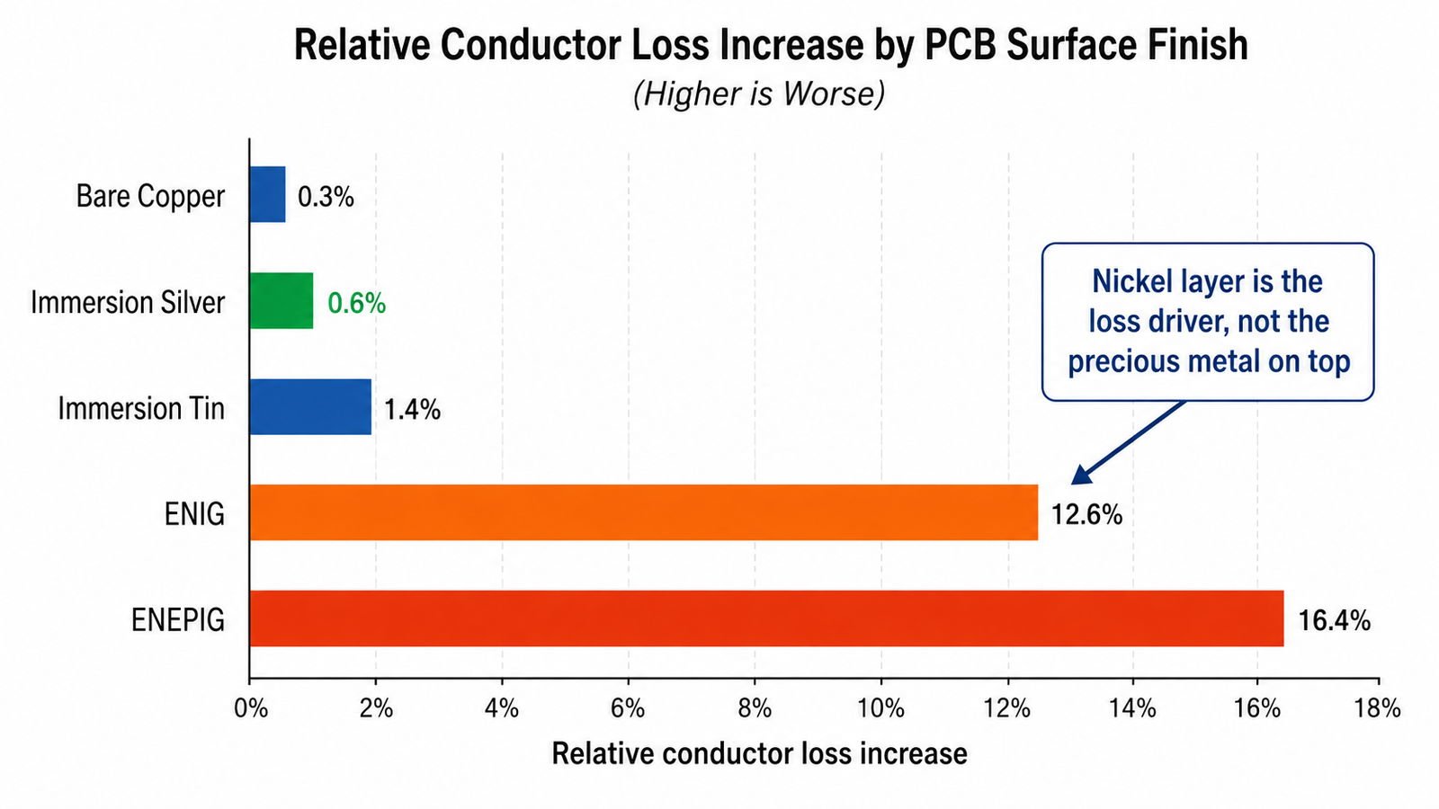
| Finish | Relative Conductor Loss (10GHz) | Skin Effect Impact | Notes |
|---|---|---|---|
| Bare copper (reference) | Baseline | — | Not practical — oxidizes rapidly |
| Immersion Silver | ~Baseline +2–4% | Minimal — silver is highly conductive | Closest to bare copper performance |
| ENIG | ~Baseline +8–15% | Nickel layer under gold adds loss | Nickel's lower conductivity is the loss driver, not the gold |
| ENEPIG | ~Baseline +8–16% | Similar to ENIG — nickel is the loss driver | Palladium layer has minimal additional impact |
| Immersion Tin | ~Baseline +3–5% | Minimal — tin conductivity acceptable | Rarely specified for RF due to shelf life |
The nickel layer in ENIG and ENEPIG increases conductor loss primarily through the skin effect: at RF frequencies, current flows predominantly in the outer skin depth of the conductor, which for a copper trace at 10GHz is only a few microns. If the nickel-gold layer thickness is comparable to or greater than the skin depth, a meaningful fraction of the RF current flows through the higher-resistivity nickel rather than the copper beneath it. This is why ENIG typically shows 8–15% higher conductor loss than bare copper or immersion silver at 10GHz, while immersion silver shows only 2–4% increase.
For most RF designs below 20GHz with moderate trace lengths, the ENIG loss penalty (8-15% conductor loss increase) is a small fraction of total insertion loss and does not change the material or design decision. For long feed networks, Ka-band and above, or designs where every 0.1dB matters, immersion silver’s lower loss can be a meaningful factor — weigh this against ENIG’s better shelf life and solderability.
Wire Bonding — Why ENEPIG Exists
ENIG has a known reliability risk for wire bonding: the electroless nickel deposition process can produce a phenomenon called ‘black pad’ — a corroded nickel surface beneath the gold that causes brittle, unreliable wire bonds or solder joints. This risk is low for standard reflow soldering but becomes significant for gold or aluminum wire bonding directly to the pad, which is common in MMIC and bare die RF assembly.
ENEPIG adds a thin palladium layer between the nickel and gold, which acts as a barrier preventing the nickel corrosion that causes black pad. This makes ENEPIG the standard choice for pads that will be wire bonded — both gold and aluminum wire bonding are supported, whereas ENIG is generally considered reliable only for gold wire bonding, and even then with more process control required.
When to Specify Each Finish
| Application | Recommended Finish | Reason |
|---|---|---|
| Standard RF microstrip, SMA connector pads | ENIG | Best balance of solderability, shelf life and acceptable loss |
| Wire bond pads (MMIC, bare die) | ENEPIG | Palladium barrier prevents black pad, supports Au and Al wire |
| Lowest insertion loss priority (Ka-band, mmWave) | Immersion Silver | No nickel layer — meaningfully lower conductor loss |
| Fine-pitch BGA / QFN on same board as RF | ENIG or ENEPIG | Flat surface needed for fine-pitch solder joint reliability |
| Cost-sensitive prototype, short shelf life OK | Immersion Tin or OSP | Lower cost, acceptable if assembled promptly |
| High humidity / long storage before assembly | ENIG | Best shelf life and tarnish resistance among RF-common finishes |
Shelf Life and Storage Considerations
- ENIG: longest shelf life among RF-common finishes — typically 12+ months under proper storage, tarnish-resistant gold surface
- ENEPIG: similar shelf life to ENIG — palladium barrier adds no significant shelf life penalty
- Immersion silver: shorter shelf life than ENIG — silver can tarnish under humidity or sulfur exposure, typically 6–12 months with proper storage, vacuum-sealed packaging recommended
- Immersion tin: shortest practical shelf life among metal finishes — tin whisker risk and oxidation over time, best used when assembly follows fabrication promptly
- OSP: shortest shelf life overall — organic coating degrades with heat cycling and time, best for immediate assembly after fabrication
Cost Considerations
ENIG is the most commonly specified finish for RF PCB and is generally competitively priced due to high production volume across the industry. ENEPIG costs modestly more than ENIG due to the additional palladium plating step. Immersion silver is typically lower cost than ENIG per unit area but requires more careful handling and packaging to protect shelf life. For most RF designs, the finish decision should be driven by technical requirements (wire bonding, insertion loss sensitivity, shelf life needs) rather than the relatively small cost difference between finishes.
Specifying Surface Finish on Your Fabrication Drawing
- State the finish explicitly: ‘ENIG per IPC-4552’ or ‘ENEPIG per IPC-4556’ — do not leave as default assumption
- For ENIG: specify gold thickness if a specific value is required (1–5 µin range) — thicker gold does not reduce conductor loss meaningfully, thickness is primarily a wire bond/wear consideration
- For wire bond pads: specify ENEPIG explicitly and confirm palladium thickness with your fabricator (typically 1–2 µin, max 20 µin per some specifications)
- For mixed finish boards (rare but possible): confirm your fabricator’s capability to selectively apply different finishes to different pad areas
ENIG vs ENEPIG vs Immersion Silver — Q&A
Common questions about surface finish insertion loss impact, wire bonding compatibility, and when to specify each finish for RF PCB.
Does ENIG surface finish increase insertion loss in RF PCB?
Yes. ENIG increases conductor loss by approximately 8-15% at 10GHz vs bare copper or immersion silver. The nickel barrier layer beneath the gold is the loss driver — nickel has lower conductivity than copper, and RF current flows predominantly in the skin depth where this layer sits. For most designs below 20GHz, this penalty is small and doesn't require changing the finish decision.
What is the difference between ENIG and ENEPIG?
ENEPIG adds a thin palladium layer between nickel and gold, preventing 'black pad' nickel corrosion that causes unreliable wire bonds. ENEPIG is standard for wire bonded pads (MMIC, bare die), supporting both gold and aluminum wire — ENIG is generally reliable only for gold wire bonding.
Which surface finish has the lowest insertion loss for RF PCB?
Immersion silver — approximately 2-4% conductor loss increase vs bare copper at 10GHz, compared to 8-15% for ENIG/ENEPIG, because it applies directly to copper with no nickel barrier. Worth considering for Ka-band and mmWave, but has shorter shelf life than ENIG.
When should I specify ENEPIG instead of ENIG for RF PCB?
Specify ENEPIG for boards with wire bond pads — MMIC or bare die components requiring gold or aluminum wire bonding. The palladium barrier prevents black pad reliability issues. For standard SMT reflow without wire bonding, ENIG is standard and cost-effective.
ENIG, ENEPIG and Immersion Silver — All Available for RF PCB
Standard ENIG for most RF designs. ENEPIG for wire bond pads. Immersion silver for lowest-loss mmWave feed lines. Confirm finish requirements during DFM review. No MOQ.
RF PCB Manufacturer → WhatsAppRequest a PCB Quote
Upload your Gerber ZIP file and project requirements. Our engineering team will review your PCB material, stackup, impedance needs, surface finish, and production quantity before quoting.
Please prepare:
- Gerber files in ZIP format
- PCB material or stackup requirements
- Controlled impedance notes if available
- Prototype or batch production quantity