
Selecting the right high frequency PCB material is the most important manufacturing decision in an RF or microwave PCB project. The material determines insertion loss, impedance stability over temperature and frequency, via reliability in thermal cycling, manufacturing complexity, and cost. Using FR4 at 5 GHz, or using a generic ‘Rogers PCB’ specification without specifying the grade, are the two most common mistakes that engineers and buyers make when specifying high frequency PCB.
This guide covers the complete range of high frequency PCB materials available from our factory — Rogers, Taconic, F4B, ZY, and Isola — with specific guidance on which material to use for each frequency band and application type.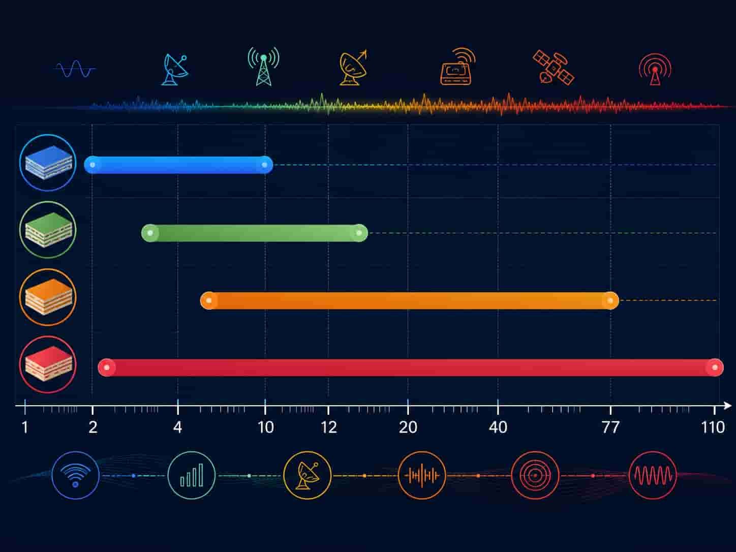
Quick Summary: Material Families at a Glance
Key point: Five material families cover the full range of high frequency PCB applications. FR4 is only suitable below 500 MHz. Rogers RO4350B hydrocarbon covers most RF applications from L-band to X-band with FR4-compatible processing. Rogers RO3003 PTFE covers Ka-band and defense applications requiring low Dk temperature variation. Rogers RT5880 PTFE covers wideband EW and W-band. Taconic TLY-5 matches RT5880 at potentially lower cost for commercial applications. F4B materials offer cost-effective PTFE for commercial designs below 15 GHz where Rogers certification is not required.
Why Standard FR4 Cannot Be Used for RF and Microwave PCB
Standard FR4 is the correct material for digital logic, power electronics, and any circuit operating below approximately 500 MHz with short signal traces. At RF frequencies, three FR4 properties become significant problems:
- High Df: FR4 Df at 10 GHz is approximately 0.020 — 5× higher than Rogers RO4350B (0.0037). This produces 5× more dielectric loss per unit length, consuming signal power as heat and degrading receiver sensitivity.
- Unstable Dk: FR4 Dk varies significantly with frequency (from ~4.8 at 1 MHz to ~4.2 at 1 GHz) and with temperature. This instability makes impedance control unreliable for broadband designs.
- Variable dielectric: FR4 Dk varies between laminate lots and manufacturers. A 50Ω trace calculated on one FR4 lot may be 48Ω or 52Ω on the next lot — unacceptable for controlled impedance RF PCB.
Rule of thumb: If your circuit operates above 1 GHz with trace lengths longer than 50mm, or above 500 MHz with trace lengths longer than 150mm, FR4 Df will produce measurable insertion loss degradation compared to Rogers or PTFE materials. Quantify the insertion loss budget before choosing FR4 for cost reasons.
The Five High Frequency PCB Material Families
1. Rogers Hydrocarbon Ceramic — The FR4-Compatible RF Material
Rogers RO4350B and RO4003C are the most widely used high frequency PCB materials globally. They provide RF performance significantly better than FR4 while processing on standard FR4-compatible equipment — no specialized hole wall activation, no PTFE-specific drill parameters.
- Rogers RO4350B: Dk 3.48, Df 0.0037 — most widely used, L-band to X-band, 5G sub-6, WiFi, VSAT
- Rogers RO4003C: Dk 3.38, Df 0.0027 — 27% lower Df than RO4350B, X-band to Ku-band
- Processing: FR4-compatible lamination, standard desmear, Rogers RO4450F bondply
- Maximum 3 lamination cycles — same as high-performance FR4
- Tg >280°C — no thermal concern in any aerospace operating range
2. Rogers PTFE — Ka-Band, EW, W-Band
Rogers RO3000 series and RT/duroid series are PTFE-based materials requiring specialized manufacturing. They provide the lowest Df of any standard PCB material and the most stable Dk over wide frequency and temperature ranges.
- Rogers RO3003: Dk 3.0, Df 0.0010 — Ka-band radar, 77 GHz automotive, defense AESA, missile seeker
- Rogers RO3003G2: Dk 3.0, Df 0.0010, tighter Dk ±0.03 — automotive radar high-volume production
- Rogers RT5880: Dk 2.2, Df 0.0009 — EW 2–18 GHz, W-band 75–110 GHz, SIGINT receivers
- Rogers RT5870: Dk 2.33, Df 0.0012 — slightly higher Dk than RT5880 for specific circuit geometry
- Processing: plasma or sodium activation required, PTFE-specific drilling, maximum 2 lamination cycles
3. Taconic PTFE — Technical Equivalent for Commercial Applications
Taconic PTFE materials match Rogers PTFE grades in electrical performance and require identical manufacturing processes. They are a viable option for commercial designs where Rogers-certified documentation is not required.
- Taconic TLP-5 / TLY-5: Dk 2.20, Df 0.0009 — direct equivalent to Rogers RT5880
- Taconic TLY-3: Dk 2.33, Df 0.0012 — direct equivalent to Rogers RT5870
- Taconic RF-35: Dk 3.5, Df 0.0018 — lower Df than Rogers RO4350B at comparable Dk
- Taconic RF-60A: Dk 6.5, Df 0.0038 — high Dk compact antenna design
- Taconic CER-10: Dk 10.0, Df 0.0035 — maximum Dk miniaturization
- All Taconic PTFE grades: same plasma activation requirement as Rogers PTFE
4. F4B — Cost-Effective PTFE for Commercial RF
F4B materials (旺灵/WangLing brand) are Chinese-manufactured PTFE laminates that provide comparable properties to Rogers at lower cost. They are suitable for commercial RF designs where Rogers brand certification is not required.
- F4BM220: Dk 2.20, Df 0.0010 — comparable to Rogers RO3003 Df, lower cost
- F4BM255: Dk 2.55, Df 0.0013 — mid-range PTFE for commercial applications
- F4BM265: Dk 2.65, Df 0.0015 — commercial RF below 15 GHz
- F4BM300: Dk 3.0, Df 0.0017 — commercial Ka-band alternative where Rogers not specified
- F4BTM400/440/615: higher Dk grades for compact antenna and filter designs
- Processing: same PTFE plasma activation required as Rogers PTFE
- Not suitable for: aerospace/defense programs requiring Rogers-certified documentation
5. ZY (中英) Materials — Rogers Alternative for Non-Certified Applications
ZY materials are Chinese-manufactured high frequency laminates covering a range of Dk values. ZYF220D matches Rogers RT5880 Df at lower cost.
- ZYF220D: Dk 2.20, Df 0.0009 — equal to Rogers RT5880 and Taconic TLP-5
- ZYF300CA-P: Dk 3.0, Df 0.0018 — higher Df than Rogers RO3003 (0.0010) — note the difference
- ZYF350CA: Dk 3.5, Df 0.0031 — lower Df than Rogers RO4350B
- Commercial applications only — not suitable for programs requiring Rogers or Taconic certification
Full Material Comparison Table
Material Selection by Application
5G Sub-6 GHz Infrastructure and Modules
- 5G base station antenna arrays (3.5 GHz): Rogers RO4350B — large panel, FR4-compatible, adequate Df
- 5G module RF PCB (below 6 GHz): Rogers RO4350B or F4B — cost-sensitive commercial designs
- 5G mmWave (24–28 GHz): Rogers RO3003 — PTFE required at mmWave frequency
- 5G mmWave (39 GHz): Rogers RO3003 on 0.254mm substrate
See: RF PCB for Wireless Communication Modules
Automotive Radar (77 GHz and 24 GHz)
- 77 GHz: Rogers RO3003 or RO3003G2 (PTFE) — standard for production automotive radar
- 77 GHz high-volume: RO3003G2 preferred — tighter Dk ±0.03 for lot-to-lot consistency
- 24 GHz short-range: Rogers RO4350B adequate at lower cost
See: High Frequency PCB for Automotive Radar and ADAS
Aerospace and Defense Radar
- L/S-band surveillance radar (1–4 GHz): Rogers RO4350B
- X-band fire control and airborne radar (8–12 GHz): Rogers RO4003C or RO3003
- Ka-band missile seeker, AESA (26.5–40 GHz): Rogers RO3003
- W-band precision radar (75–110 GHz): Rogers RT5880
See: High Frequency PCB for Aerospace and Defense
Electronic Warfare (EW) Systems
- ESM/RWR/SIGINT covering 2–18 GHz: Rogers RT5880 or Taconic TLP-5 — minimum Df across full band
- ECM jamming amplifiers: Rogers RT5880 — power handling at EW frequencies
- Airborne EW: Rogers RT5880, IPC Class 3, Rogers-certified documentation
- Commercial EW simulation/test: Taconic TLP-5 viable alternative at lower cost
See: Rogers PCB for Electronic Warfare Systems
Satellite Communication
- C-band ground terminal (3.7–4.2 GHz): Rogers RO4350B
- Ku-band VSAT (10.7–14.5 GHz): Rogers RO4003C or RO3003
- Ka-band HTS terminal (17–30 GHz): Rogers RO3003
- Space-borne electronics: Rogers RO3003 or RT5880 — must pass ASTM E595 outgassing
See: High Frequency PCB for Satellite Communication and Space
Commercial IoT and Industrial RF
- IoT devices below 5 GHz: F4BM220 or F4BM255 — cost-effective PTFE
- Industrial radar sensors (24 GHz): F4BM220 or ZYF220D
- WiFi and Bluetooth modules: Rogers RO4350B or F4B — cost depends on volume
- Commercial applications where Rogers brand not required: ZY or F4B viable
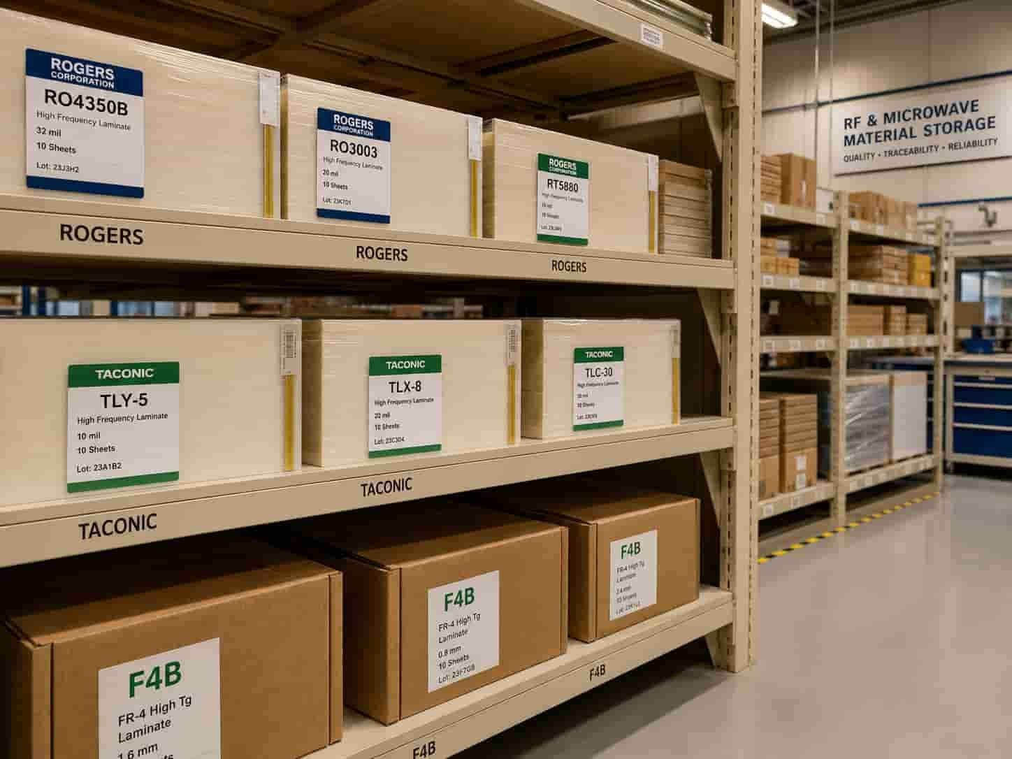
Manufacturing Process Requirements by Material Family
Understanding which materials require PTFE-specific processing helps verify that your chosen factory can reliably produce the specified material.
FR4-Compatible Processing (Rogers RO4350B, RO4003C)
- Standard FR4 lamination equipment — widely available
- Standard permanganate desmear process
- Rogers RO4450F or RO4450T bonding film — must be in factory stock
- Maximum 3 lamination cycles
- Widely available from most PCB factories — ask about RO4450F stock to confirm genuine capability
PTFE Process Required (Rogers RO3003, RT5880, Taconic, F4B PTFE)
- Hole wall activation: plasma etch or sodium naphthalene — mandatory before copper plating
- PTFE-specific drill spindle speed and feed rate — standard FR4 parameters cause deformation
- PTFE-compatible lamination press profile
- Rogers 2929 bondply for Rogers PTFE, tacBOND for Taconic
- Maximum 2 lamination cycles strictly — 3rd cycle degrades PTFE properties
- Fewer factories have this capability — verify with process questions before ordering
For factory verification guidance, see How to Evaluate a High Frequency PCB Manufacturer.
High Frequency PCB Materials Available at Riching PCB
As a direct high frequency PCB factory with both FR4-compatible and PTFE process lines, we hold the following materials in regular production inventory:
Rogers Materials
- RO4350B, RO4003C — hydrocarbon ceramic, FR4-compatible process
- RO3003, RO3003G2, RO3006, RO3010 — PTFE ceramic, plasma activation
- RT5880, RT5870 — PTFE glass, plasma activation
- RO6010 — ceramic PTFE, high Dk
Taconic Materials
- TLY-5A, TLP-5, TLY-5, TLY-3 — ultra-low loss PTFE glass
- RF-35, RF-60A, CER-10 — general RF and high Dk PTFE
F4B Materials
- F4BM220, F4BM255, F4BM265, F4BM300 — PTFE laminates
- F4BTM400, F4BTM440, F4BTM615 — higher Dk F4B grades
ZY Materials
- ZYF220D, ZYF225DA, ZYF265D, ZYF300CA-P, ZYF350CA
Manufacturing Capability
- Controlled impedance: ±10% standard, ±8% advanced — TDR verified every lot
- Minimum drill: 0.1mm advanced, 0.2mm standard
- Aspect ratio: 14:1 advanced, 10:1 standard
- Layer count: 2–32 standard, up to 50 advanced
- IPC Class 3: available for aerospace and defense programs
- Hybrid stackups: Rogers + FR4, PTFE + FR4, Rogers + Rogers hybrid
What to Prepare Before Requesting a High Frequency PCB Quote
- Material family and specific grade — or operating frequency for material recommendation
- Substrate thickness — confirm standard availability before stackup finalization
- Complete stackup with layer sequence, copper weight, and dielectric thickness
- Controlled impedance requirements — target value, tolerance, and layer
- Operating frequency or frequency range
- Application type — commercial, aerospace, defense, or automotive
- IPC Class requirement — Class 2 or Class 3
- Rogers-certified documentation required? (defense/aerospace programs)
- Surface finish — ENIG, ENEPIG, or immersion silver
- Quantity — prototype or production
For a complete file checklist, see What Files Are Needed for a High Frequency PCB Quotation?. For Rogers-specific selection guidance, see Rogers PCB Material Selection Guide.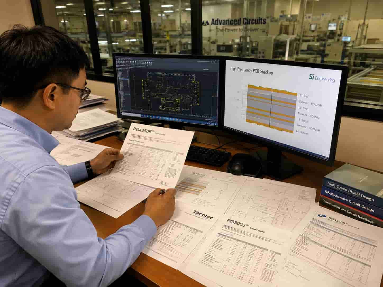
Conclusion
High frequency PCB material selection starts with operating frequency and application type. Rogers RO4350B covers the majority of RF and microwave applications below X-band with FR4-compatible manufacturing. Rogers RO4003C extends to Ku-band where tighter loss budget is needed. Rogers RO3003 and equivalent PTFE materials are required for Ka-band, 77 GHz, and defense applications. Rogers RT5880 and Taconic TLP-5 provide minimum loss for wideband EW and W-band. F4B and ZY materials offer cost-effective options for commercial designs where Rogers-certified documentation is not required.
As a direct high frequency PCB factory with Rogers, Taconic, F4B, and ZY production in our own process lines — including both FR4-compatible and PTFE plasma activation capability — we review material specifications before every order and confirm the correct material for your application before production begins.