Ground-based air defense systems are among the most complex and high-value defense electronic programs. They encompass long-range surveillance radar, precision fire control radar, missile command uplink systems, target tracking radar, and the command and control electronics that integrate all these functions into a coordinated air defense network. Each subsystem places different and specific demands on the high frequency PCB that forms its RF front-end.
Unlike airborne or missile electronics, ground-based air defense systems operate continuously in fixed or semi-mobile installations over service lives that may span 20–30 years. The high frequency PCB inside these systems must perform reliably across the full range of outdoor environmental conditions — from desert heat to arctic cold, from salt air near coastlines to dust in arid environments — while maintaining the RF performance that determines the system’s ability to detect and engage threats.
This guide covers the radar subsystem types used in ground-based air defense, Rogers PCB material selection by frequency band, phased array antenna feed network design, high-power GaN transmitter thermal management, environmental requirements, IPC Class 3 manufacturing standards, and what to confirm before production.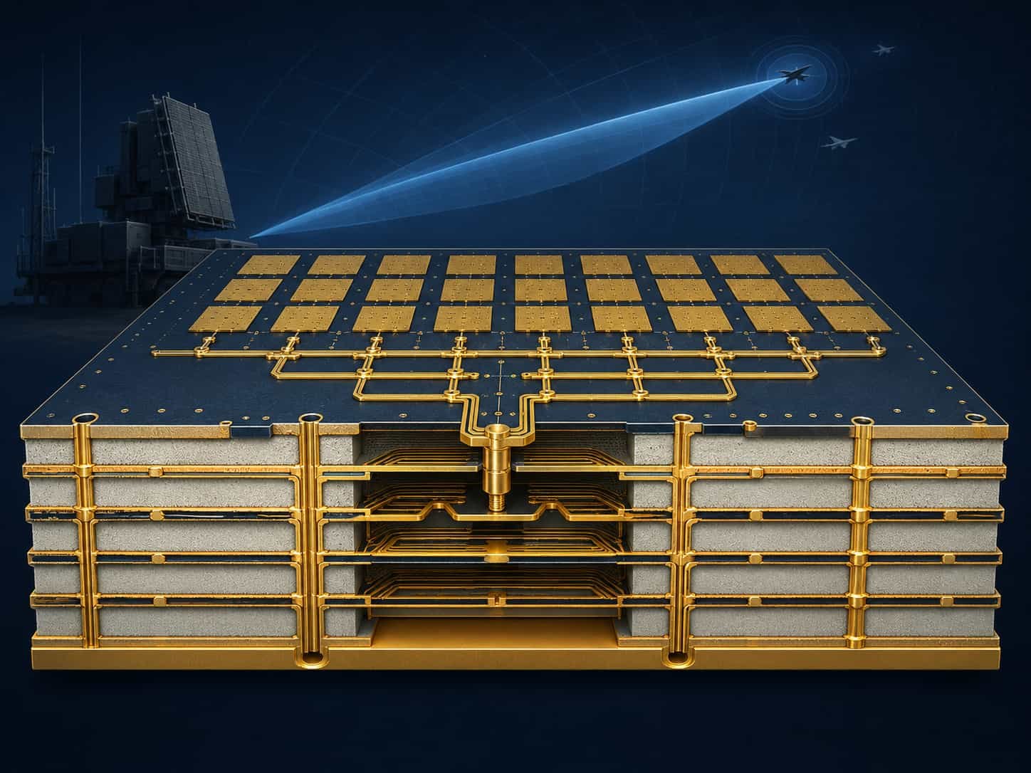
Quick Summary
Key point: Ground-based air defense radar PCB spans S-band surveillance radar using Rogers RO4350B, X-band fire control radar using Rogers RO4003C or RO3003, and Ka-band terminal defense radar using Rogers RO3003. Phased array T/R module PCB requires tight Dk tolerance for phase consistency, high-power GaN thermal management, and IPC Class 3 workmanship. Long service life (20–30 years), outdoor environmental exposure, and MIL-STD-810 qualification distinguish ground-based air defense from shorter-life airborne and missile electronics.
Ground-based air defense PCB has different priority weightings than missile or space PCB. Cost per board is less critical than total system reliability over a long service life. Repairability is possible — unlike missiles — so PCB must support field maintenance and component replacement. But the consequence of system failure in a threat environment is severe, so IPC Class 3, full traceability, and rigorous environmental qualification remain the standard.
Ground-Based Air Defense Subsystems and PCB Requirements
A complete ground-based air defense system integrates multiple radar and electronic subsystems, each with its own frequency band and PCB requirements.
Long-Range Surveillance Radar (L-Band and S-Band)
Long-range surveillance radar provides early warning detection of airborne threats at ranges up to several hundred kilometers. L-band (1–2 GHz) and S-band (2–4 GHz) provide good detection range and weather penetration. These are among the largest radar systems, with phased array antenna apertures spanning several meters.
- L-band surveillance radar (1–2 GHz): Rogers RO4350B or high-quality FR4 hybrid — lower frequency reduces Rogers material requirement
- S-band surveillance radar (2–4 GHz): Rogers RO4350B — most common choice for S-band air defense surveillance
- PCB size: large antenna array PCB — panel sizes up to the maximum manufacturing capability
- Power level: high average power — GaN or klystron transmitter, high-power T/R modules
- Duty cycle: typically low pulse duty cycle but continuous operation — thermal management for average power
Medium-Range Tracking and Fire Control Radar (C-Band and X-Band)
Medium-range tracking radar provides precision tracking of detected threats for fire control guidance. C-band (4–8 GHz) and X-band (8–12 GHz) provide the angular resolution and tracking precision needed for engagement of fast-moving targets. These radars are smaller than surveillance radars but require higher precision in antenna beam pointing and range measurement.
- C-band fire control radar (4–8 GHz): Rogers RO4003C — lower Df than RO4350B for longer feed networks
- X-band fire control and tracking radar (8–12 GHz): Rogers RO4003C or RO3003
- Phased array: tight phase matching across T/R elements for precise beam pointing
- Pulse-Doppler processing: high-dynamic-range ADC interface on PCB
- Multiple beam: simultaneous tracking of multiple targets — complex signal processing PCB
Terminal Defense Radar (Ka-Band)
Terminal defense radar for close-in weapon systems (CIWS) and short-range interceptor guidance operates at Ka-band (26.5–40 GHz) for high angular resolution at short range. The PCB at Ka-band requires Rogers RO3003 and manufacturing tolerances approaching those of missile seeker PCB.
- Ka-band terminal defense (26.5–40 GHz): Rogers RO3003 — Dk 3.0, Df 0.0010
- Minimum line width: 2.5–3 mil for Ka-band antenna feed structures
- High rotation rate: Ka-band mechanically scanned systems may rotate at high speed — vibration on PCB
- Short range, high update rate: radar must detect and track fast targets at close range
Missile Command Uplink and Datalink
Air defense missiles receive guidance commands via radio uplink from the ground system throughout their flight. The command uplink transmitter PCB must handle moderate RF power at S-band or X-band with high reliability — a failed uplink means a lost interceptor.
- Command uplink frequency: typically S-band or X-band
- Rogers RO4350B or RO4003C — adequate for uplink transmitter PCB at these frequencies
- Reliability: uplink transmitter failure ends engagement — high reliability design essential
- IPC Class 3 minimum — some programs specify above Class 3 for uplink electronics
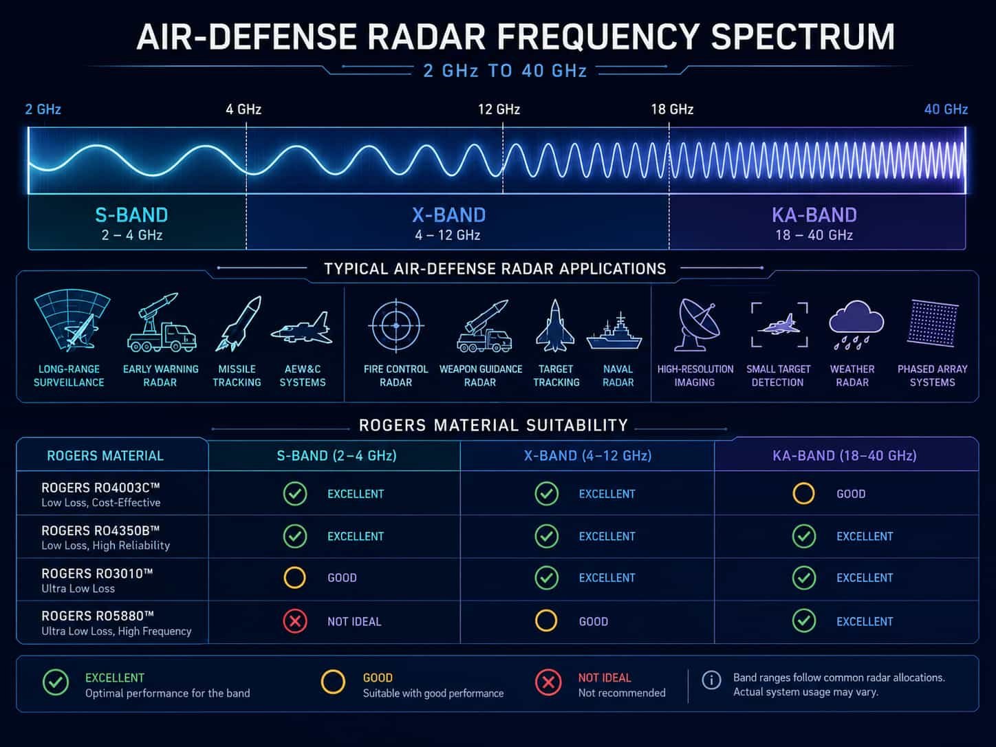
Rogers PCB Material Selection for Air Defense Radar
Rogers material selection for ground-based air defense PCB follows the same frequency-driven logic as airborne radar, but with some differences driven by the larger board size, longer service life, and outdoor environmental requirements of ground-based systems.
Rogers RO4350B — S-Band and C-Band Air Defense
Rogers RO4350B is the standard material for S-band surveillance radar and C-band fire control radar PCB. Its Tg of >280°C, compatibility with standard FR4 lamination processes, and cost-effectiveness for large-panel production make it well suited for the large antenna array PCB used in ground-based radar.
- Frequency range: up to approximately 30–40 GHz — adequate for S-band and C-band air defense
- Dk: 3.48 ±0.05, Df: 0.0037 at 10 GHz
- Large panel compatibility: available in panel sizes compatible with large air defense array production
- Hybrid with FR4: RO4350B + FR4 hybrid stackup commonly used for large air defense array PCB to reduce cost
- Service life: >280°C Tg ensures long-term thermal stability over 20–30 year service life
Rogers RO4003C — C-Band and X-Band Fire Control
Rogers RO4003C (Dk 3.38, Df 0.0027) provides lower insertion loss than RO4350B for C-band and X-band fire control radar where the feed network may be several hundred millimeters long.
- Lower Df (0.0027 vs 0.0037) reduces feed network insertion loss at C-band and X-band
- Dk 3.38 ±0.05 — slightly lower than RO4350B, compatible with same PCB design rules
- Applications: X-band fire control radar T/R module PCB, C-band tracking radar feed networks
- Compatible with RO4350B lamination process — can be used in same hybrid stackup
Rogers RO3003 — X-Band and Ka-Band Precision Tracking
Rogers RO3003 is used for the highest-frequency air defense radar applications including Ka-band terminal defense and X-band precision tracking where minimum insertion loss is required over long antenna feed networks.
- Dk: 3.0 ±0.04, Df: 0.0010 — lowest loss among commonly used air defense materials at X-band and above
- x-y CTE: 17 ppm/°C — excellent dimensional stability for large-format phased array PCB
- Tg: >500°C (PTFE base) — no glass transition concern across any outdoor operating temperature range
- Applications: Ka-band terminal defense PCB, X-band precision tracking radar with long feed networks
For Rogers material properties and selection detail, see Rogers PCB Material Selection Guide for RF and Microwave Applications. For aerospace and defense material overview, see High Frequency PCB for Aerospace and Defense: Material, Reliability and Manufacturing Requirements.
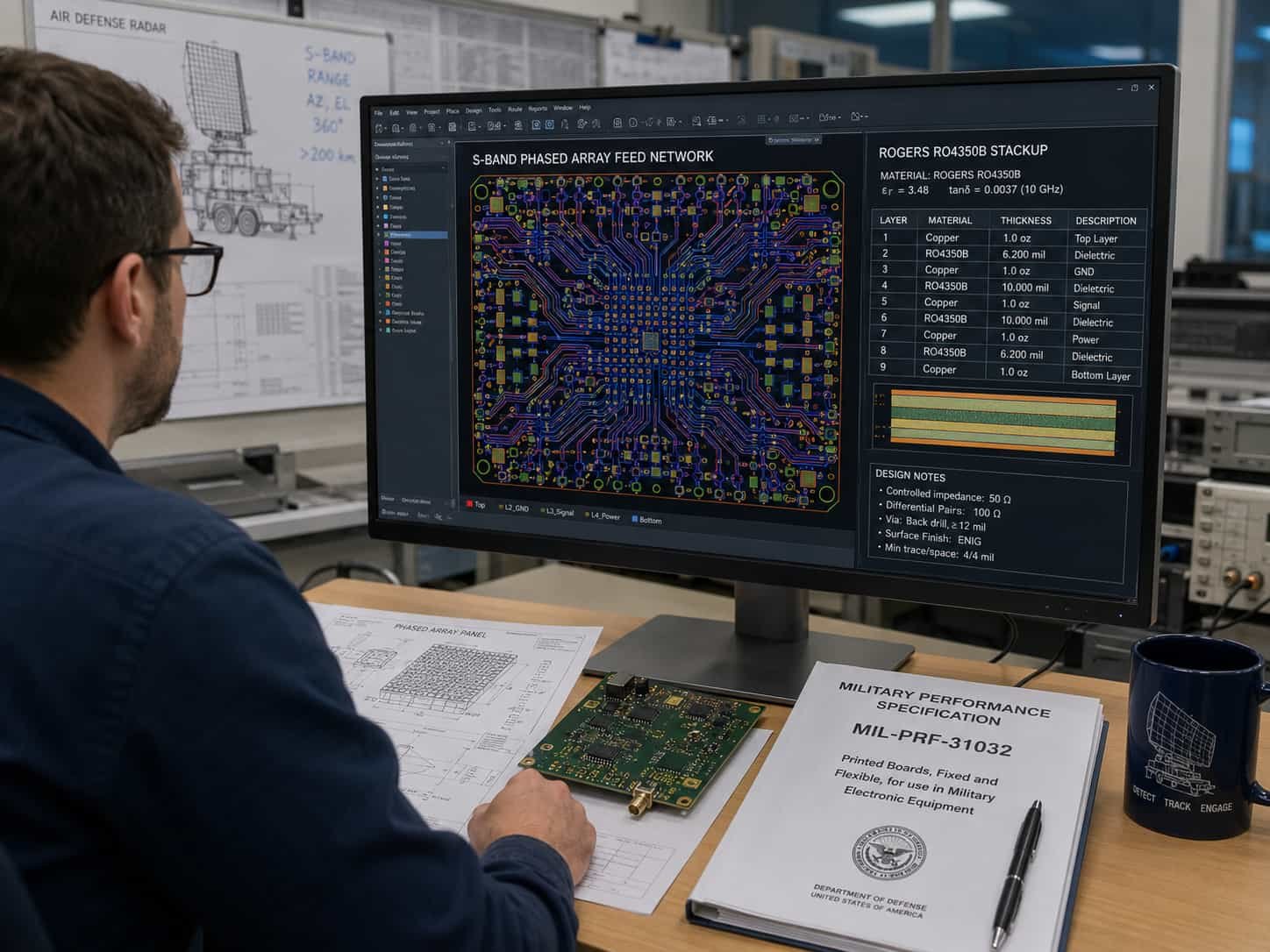
Phased Array Radar PCB for Ground-Based Air Defense
Modern ground-based air defense radar increasingly uses active electronically scanned array (AESA) technology for its advantages in beam agility, simultaneous multi-function operation, and high reliability with no moving parts. The PCB requirements for ground-based AESA air defense are similar to airborne AESA but with some important differences driven by scale and service life.
Large-Format Phased Array PCB
Ground-based air defense phased arrays are much larger than airborne arrays. An S-band air defense array may have hundreds or thousands of T/R elements across a several-meter aperture. The PCB for the antenna feed network may be a very large panel — approaching the maximum manufacturing panel size.
- Array aperture: 1–10 m for S-band and X-band ground-based air defense arrays
- T/R element count: hundreds to thousands of elements for large arrays
- Panel size: feed network PCB may approach maximum manufacturing panel — 480 × 800 mm standard, larger by engineering review
- Feed network loss: cumulative insertion loss across the large feed network directly affects sensitivity — material Df critical
- Phase consistency: all feed paths from center to edge must be equal electrical length for correct beam pointing
T/R Module PCB for Ground-Based AESA
Each T/R element in a ground-based AESA has a dedicated T/R module PCB. For large arrays, T/R module cost is a significant system cost driver — material and manufacturing cost per module must be managed while maintaining performance.
- T/R module frequency: matched to array frequency — S-band, X-band, or Ka-band
- GaN T/R module: GaN MMIC provides high power efficiency and reliability for ground-based AESA
- Power dissipation: GaN T/R modules dissipate 3–15W each — large array total thermal load is substantial
- Cooling: ground-based systems can use forced air, liquid cooling, or thermoelectric cooling — less constrained than airborne
- Module cost: for thousands of modules, Rogers material grade selection directly affects total array PCB cost
Phase Matching Across Large Array
In a large ground-based phased array, maintaining equal electrical length for all feed paths from the central signal source to each T/R element is a critical manufacturing challenge. Any phase error between elements degrades beam quality, increases sidelobes, and reduces radar sensitivity.
- Phase error budget: typically ±5–10 degrees per element at operating frequency — tighter for precision tracking radar
- Dk tolerance: Dk variation between production lots affects electrical length — Rogers Dk tolerance ±0.05 or better
- Temperature compensation: Dk temperature coefficient of Rogers material causes phase shift over outdoor temperature range — must be compensated or budgeted
- Rogers RO4350B Dk temperature coefficient: +50 ppm/°C — phase shift over -40°C to +85°C outdoor range must be analyzed
- Rogers RO3003 Dk temperature coefficient: +13 ppm/°C — 4× more stable than RO4350B over temperature
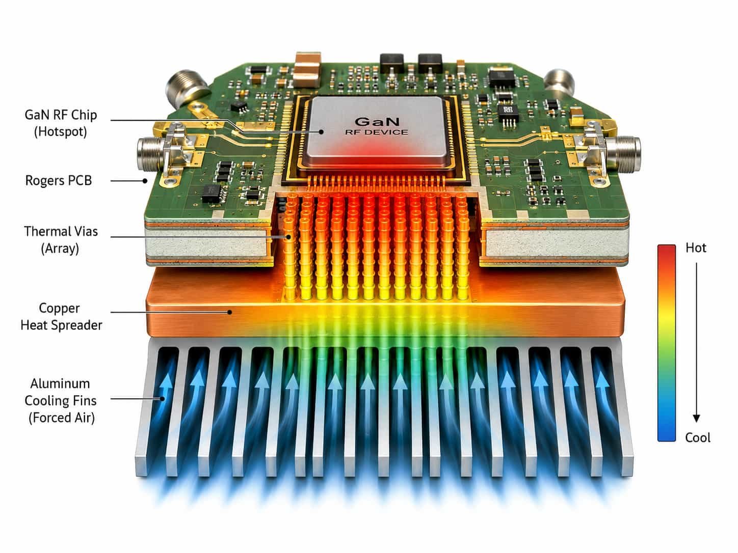
High-Power RF and GaN Thermal Management
Ground-based air defense radar transmitters generate significantly higher peak and average RF power than airborne or missile systems. Managing the heat from GaN power amplifiers across a large array is one of the primary engineering challenges for ground-based AESA air defense PCB.
GaN Power Amplifier Characteristics
- GaN T/R module peak power: typically 10–50W per element at S-band, lower at X-band and Ka-band
- Average power: depends on duty cycle — ground-based radar may operate at 10–20% duty cycle continuously
- Power density: GaN chips may dissipate 5–20 W/mm² — very high thermal density
- Junction temperature: GaN HEMT junction must remain below 200°C — PCB thermal resistance determines margin
- Reliability impact: every 10°C reduction in junction temperature approximately doubles GaN device lifetime — critical for 20–30 year service life
PCB Thermal Management for Ground-Based Air Defense
Ground-based systems have more thermal management options than airborne or missile systems — they can use larger heat sinks, forced-air cooling, and even liquid cooling. The PCB design must still manage heat efficiently to the chassis interface.
- Thermal via array: 0.2–0.3 mm diameter, 0.5–0.8 mm pitch under GaN chip package
- Rogers RO4350B thermal conductivity: 0.69 W/m·K — highest of common Rogers materials
- Rogers RO3003 thermal conductivity: 0.50 W/m·K — moderate
- Copper coin insert: for highest-power GaN modules where standard via array thermal resistance is insufficient
- Internal copper planes: maximize copper fill on ground planes adjacent to transmit layers
- Chassis interface: PCB ground plane must make reliable low-resistance contact to the chassis — affects both thermal and EMC performance
Environmental Requirements for Ground-Based Air Defense PCB
Ground-based air defense systems are deployed in a wide range of geographic and climatic environments. The PCB must maintain RF performance and mechanical integrity across all specified environmental conditions throughout the system service life.
Temperature Range
- Operating temperature: typically -40°C to +55°C ambient for outdoor ground-based systems
- Internal equipment temperature: may reach +85°C with electronics self-heating in closed shelters
- Storage temperature: -55°C to +71°C
- Daily thermal cycling: outdoor systems experience one thermal cycle per day — 10,000+ cycles over 30-year life
- Rogers RO4350B Tg > 280°C: well above any ground-based operating temperature — no concern
- Rogers RO3003 PTFE base: no Tg — excellent long-term stability
Humidity and Salt Fog
- Coastal deployment: salt fog exposure — conformal coating essential for PCB protection
- Tropical deployment: 95% RH at 40°C — conformal coating, sealed enclosures
- IEC 60068-2-52 / MIL-STD-810 Method 509.6: salt fog testing for coastal deployment
- Rogers PTFE materials: hydrophobic — low moisture absorption compared to FR4 — advantage in high-humidity environments
Dust and Sand
- Arid and desert deployment: fine dust and sand ingress
- IP65 or higher enclosure rating typically required for ground-based outdoor radar electronics
- Conformal coating protects PCB from dust accumulation affecting electrical performance
- Ventilation filters: forced-air cooled enclosures require air filtration in dusty environments
MIL-STD-810 Environmental Qualification
- Method 501.7: high temperature
- Method 502.7: low temperature
- Method 507.6: humidity
- Method 509.6: salt fog
- Method 510.7: sand and dust
- Method 514.8: vibration — ground vehicle transport and generator vibration
- Method 516.8: shock — handling drops and transport
Long Service Life Requirements for Air Defense PCB
Ground-based air defense systems are designed for 20–30 year service lives. This distinguishes them from missile electronics (single-use) and some airborne electronics (10–15 years) and places unique requirements on PCB material selection, solder joint design, and conformal coating.
Solder Joint Fatigue Over 30 Years
With one thermal cycle per day in outdoor operation, a 30-year ground-based radar system experiences approximately 10,000 thermal cycles. This is comparable to the lifetime thermal cycling requirement for many space systems, placing demanding requirements on solder joint design and PCB CTE management.
- 10,000 thermal cycles from -40°C to +55°C or -40°C to +85°C — equivalent to 30 years outdoor operation
- Solder joint fatigue life: must be demonstrated by thermal cycling qualification to the full service life equivalent
- Component lead compliance: compliant leads (J-leads, gull-wing) are more forgiving of CTE mismatch than leadless components
- Underfill: for large leadless BGA and QFN components, underfill significantly extends thermal cycling fatigue life
- Rogers RO4350B x-y CTE: 14–17 ppm/°C — close to FR4 and most component packages — good solder joint fatigue performance
Conformal Coating for Long-Life Protection
Conformal coating is standard for ground-based air defense PCB to protect against 30 years of humidity, temperature cycling, and environmental contamination. Coating selection must consider the full service life and any required maintenance or repair procedures.
- Acrylic coating: most common for ground-based radar — easy to rework for field repair, good humidity protection
- Polyurethane: good chemical resistance for dusty or chemically contaminated environments
- Silicone: for high-temperature locations near power electronics — -65°C to +200°C range
- Reworkability: acrylic and polyurethane are reworkable for field component replacement — important for long-service-life systems
- Coverage inspection: AOI or UV inspection of conformal coating after application — no bare areas permitted on coated PCB
IPC Class 3 and Quality Requirements for Air Defense PCB
IPC Class 3 is the baseline for all ground-based air defense high frequency PCB. The combination of long service life, outdoor environmental exposure, and mission-critical system function makes anything below Class 3 inappropriate.
- PTH copper plating: 25 µm average, 20 µm minimum — for 30-year thermal cycling life
- No annular ring breakout: ensures reliable via connections throughout service life
- 5% maximum void: limits plating defects that become fatigue initiation sites
- 100% electrical test: every board tested before installation
- First article inspection: microsection, plating thickness, surface finish measurement
- Impedance coupon verification: TDR measurement every production lot
- Traceability: material certificates, laminate lot numbers, process records — retained for system service life
- MIL-PRF-31032: applicable to US military air defense PCB programs
For IPC Class 3 details, see IPC Class 3 High Frequency PCB: What It Means for Aerospace and Defense Applications. For wide temperature range and long service life requirements, see Wide Temperature Range PCB: Material and Manufacturing for Aerospace Applications.
Information Needed for Ground-Based Air Defense PCB Quotation
To review feasibility and provide an accurate quotation for ground-based air defense high frequency PCB, the following information should be prepared:
- Gerber files (all layers) and NC drill files
- Complete PCB stackup with Rogers material grade, layer sequence, and copper weight
- Air defense subsystem type — surveillance radar, fire control, tracking, command uplink
- Operating frequency band — L/S-band, C-band, X-band, Ka-band
- PCB dimensions — panel size and finished board size
- Layer count and board thickness
- Via structure — through-hole, blind, buried, T/R module thermal vias
- Controlled impedance requirements including phase matching tolerance if applicable
- GaN chip power dissipation and thermal management requirement
- Outdoor environmental exposure — deployment region, MIL-STD-810 test requirements
- Service life requirement — years of outdoor operation and daily thermal cycles
- Conformal coating type and coverage requirement
- IPC Class 3 and any above-Class-3 requirements
- Applicable standards — MIL-PRF-31032, MIL-STD-810, MIL-STD-461
- Traceability and record retention requirements
- Quantity — prototype, qualification lot, or production
For a complete file checklist, see What Files Are Needed for a High Frequency PCB Quotation?. For radar system PCB requirements, see High Frequency PCB for Radar Systems: EW, AESA and Ground-Based Radar.
Conclusion
Ground-based air defense PCB spans S-band surveillance radar using Rogers RO4350B, X-band fire control and tracking radar using Rogers RO4003C or RO3003, and Ka-band terminal defense using Rogers RO3003. Large-format phased array antenna feed networks, high-power GaN T/R module thermal management, phase consistency across thousands of elements, and 20–30 year outdoor service life are the defining requirements that distinguish ground-based air defense from other defense radar applications.
IPC Class 3 workmanship, MIL-STD-810 environmental qualification, conformal coating for outdoor protection, long-service-life solder joint design, and full material traceability are the manufacturing framework for high frequency PCB in ground-based air defense systems. Early engagement with a manufacturer experienced in large-format Rogers PCB, GaN thermal management, and defense qualification significantly reduces program risk during development and qualification.