Aerospace and defense electronics operate in one of the most thermally demanding environments of any electronic application. An aircraft avionics system may be powered on at -55°C on a cold arctic morning and reach +85°C or higher during sustained operation. A missile guidance system may experience even wider temperature extremes during its operational profile. Ground-based radar equipment in desert environments cycles between cold nights and hot days throughout its service life.
For high frequency PCB used in these applications, temperature variation is not just a reliability concern — it directly affects electrical performance. Dielectric constant (Dk) changes with temperature, which shifts the impedance of RF transmission lines and the resonant frequency of antenna elements. Dimensional changes from thermal expansion affect layer registration, via reliability, and connector fit. Materials that perform well at room temperature may degrade significantly at temperature extremes.
This guide covers the key material properties, design considerations, and manufacturing requirements for high frequency PCB that must operate reliably across wide temperature ranges in aerospace and defense applications.
Quick Summary
Key point: Rogers RO3003 and RT5880 PTFE materials have no glass transition temperature in the aerospace operating range, making them the most stable choice for -55°C to +125°C or wider. Rogers RO4350B offers Tg > 280°C and good thermal stability for most airborne applications. Standard FR4 (Tg 130–170°C) is not suitable for high frequency layers in aerospace designs. CTE mismatch between PCB material and copper causes via fatigue in thermal cycling — z-axis CTE is the critical parameter to manage.
Wide temperature range performance for aerospace high frequency PCB requires matching three properties simultaneously: electrical stability (Dk temperature coefficient), mechanical stability (CTE matching between layers and materials), and structural integrity (Tg well above the maximum operating temperature). No single material optimizes all three properties — the choice involves tradeoffs that must be evaluated for each application.
Why Wide Temperature Range Is Critical for Aerospace High Frequency PCB
Electrical Performance Variation with Temperature
The dielectric constant (Dk) of PCB materials changes with temperature. For a controlled impedance transmission line, a change in Dk changes the effective electrical length of the line and shifts the characteristic impedance. For an antenna element, a Dk change shifts the resonant frequency. These effects become more significant as frequency increases and as the temperature excursion widens.
- Typical Dk temperature coefficient for Rogers RO4350B: +50 ppm/°C (Dk increases with temperature)
- Typical Dk temperature coefficient for Rogers RO3003: +13 ppm/°C — much more stable
- Typical Dk temperature coefficient for Rogers RT5880: -125 ppm/°C (Dk decreases slightly with temperature)
- Over a -55°C to +125°C range (180°C total), RO4350B Dk may shift by approximately 0.9%
- Over the same range, RO3003 Dk shifts by approximately 0.2% — 4.5× more stable
Dimensional Change with Temperature
All PCB materials expand and contract with temperature. The coefficient of thermal expansion (CTE) determines how much the material changes dimensions per degree of temperature change. For multilayer PCB, CTE mismatch between the laminate and copper conductors causes stress on the copper traces and via barrels during thermal cycling.
- Copper CTE: approximately 17 ppm/°C — relatively stable
- Rogers RO3003 x-y CTE: 17 ppm/°C — matches copper closely in x-y plane
- Rogers RO4350B x-y CTE: 14–17 ppm/°C — good match to copper in x-y plane
- Standard FR4 z-axis CTE: 50–70 ppm/°C — very high z-axis expansion strains PTH via barrels
- Rogers RT5880 x-y CTE: 31 ppm/°C — higher than copper, must be managed in large array designs
Glass Transition Temperature (Tg)
The glass transition temperature (Tg) is the temperature at which the resin in the laminate transitions from a rigid, glassy state to a softer, rubbery state. Above Tg, the material’s CTE increases dramatically — often by 3–5 times — which accelerates via barrel fatigue and delamination. The operating temperature must always be well below Tg.
- Standard FR4 Tg: 130–170°C — too close to aerospace operating range upper limits
- Rogers RO4350B Tg: >280°C — well above any aerospace operating temperature
- Rogers RO3003 Tg: >500°C (PTFE base — no glass transition) — excellent for extreme temperature
- Rogers RT5880 Tg: >500°C (PTFE base — no glass transition) — suitable for widest temperature range
Key point: For aerospace applications requiring operation above +125°C, PTFE-based materials (Rogers RO3003, RT5880, Taconic TLY-5) are strongly preferred because they have no glass transition temperature in any practical aerospace operating range. Rogers RO4350B with Tg > 280°C is also suitable for most airborne applications up to +150°C storage.
Material Comparison for Wide Temperature Range Aerospace PCB
The table below compares key thermal properties of common high frequency PCB materials used in aerospace and defense applications. These properties directly affect electrical performance stability and mechanical reliability across wide temperature ranges.
Rogers RO3003: Best Balance for Aerospace Wide Temperature Range
Rogers RO3003 offers the best combination of thermal stability properties for aerospace high frequency PCB. Its PTFE base eliminates glass transition concerns, its low Dk temperature coefficient minimizes electrical performance variation, and its CTE closely matches copper in the x-y plane.
Key Thermal Properties of RO3003
- Dk: 3.0 ±0.04 — consistent across production lots and temperature
- Dk temperature coefficient: +13 ppm/°C — lowest among standard Rogers laminates
- z-axis CTE: 24 ppm/°C — lower than most PTFE materials, reduces via stress
- x-y CTE: 17 ppm/°C — closely matches copper, minimizes trace and antenna dimensional shift
- Tg: >500°C (PTFE base) — no glass transition in any aerospace temperature range
- Operating temperature range: -55°C to +150°C continuous
- Thermal conductivity: 0.50 W/m·K — moderate, adequate for most airborne RF modules
Applications Where RO3003 Excels
- Airborne radar PCB operating at X-band through Ka-band over -55°C to +125°C range
- Phased array antenna PCB where phase consistency over temperature is critical
- Electronic warfare receiver PCB requiring stable Dk across wide temperature and frequency range
- Missile guidance and seeker PCB operating in extreme temperature environments
- Satellite communication PCB where temperature stability affects link budget
Rogers RT5880: Ultra-Low Loss Across Temperature
Rogers RT5880 provides the lowest Dk (2.2) and Df (0.0009) of standard aerospace PCB materials. Its PTFE base gives it the same excellent glass transition characteristics as RO3003. The trade-off is a higher x-y CTE of 31 ppm/°C, which must be managed in designs with large antenna apertures or long transmission lines.
Key Thermal Properties of RT5880
- Dk: 2.2 ±0.02 — lowest standard aerospace PCB material, negative temperature coefficient
- Dk temperature coefficient: -125 ppm/°C — Dk decreases slightly with temperature
- z-axis CTE: 237 ppm/°C — very high z-axis expansion, via reliability must be carefully managed
- x-y CTE: 31 ppm/°C — higher than copper, causes dimensional shift in large arrays over temperature
- Tg: >500°C (PTFE base)
- Operating temperature: -55°C to +150°C continuous
Managing RT5880 CTE in Wide Temperature Range Designs
The high z-axis CTE of RT5880 (237 ppm/°C) places more stress on via barrels during thermal cycling than RO3003 or RO4350B. For aerospace applications requiring RT5880 — such as W-band radar or very low loss EW systems — via design and thermal cycling qualification are especially important.
- Use thinner RT5880 substrates where possible to reduce absolute via barrel stress
- Increase via barrel copper plating thickness — 25 µm or above for Class 3
- Thermal cycling qualification to the full operating temperature range before production release
- Microsection analysis after thermal cycling qualification to verify via barrel integrity
Rogers RO4350B: Cost-Effective for Moderate Aerospace Requirements
Rogers RO4350B is suitable for most airborne and ground-based defense electronics operating up to approximately 30–40 GHz where the operating temperature range does not exceed +150°C. Its hydrocarbon ceramic base provides Tg > 280°C, which is well above typical airborne operating temperatures, and its manufacturing compatibility with standard FR4 processes makes it cost-effective for moderate volume programs.
- Dk: 3.48 ±0.05 — slightly higher Dk temperature coefficient than RO3003
- Dk temperature coefficient: +50 ppm/°C — acceptable for L-band to X-band; tighter budgets may require RO3003
- z-axis CTE: 32–46 ppm/°C — higher than RO3003, more via stress in thick boards
- Tg: >280°C — excellent thermal stability for standard aerospace operating range
- Compatible with standard FR4 multilayer lamination — cost-effective for hybrid stackups
- Applications: L-band to X-band airborne radar, avionics communication PCB, defense RF modules
Why Standard FR4 Is Not Suitable for Aerospace High Frequency Layers
Standard FR4 laminate is the most common PCB material in commercial electronics, but it is not suitable for RF signal layers in aerospace and defense high frequency PCB for several reasons:
- Dk: 4.3–4.8 — high and variable, unsuitable for precision RF impedance control
- Df: 0.015–0.025 — 10–25× higher than Rogers materials, unacceptable insertion loss at microwave frequencies
- Tg: 130–170°C (standard) — too close to aerospace upper operating and storage temperatures
- Dk temperature coefficient: high and variable — RF electrical performance shifts significantly over temperature
- z-axis CTE: 50–70 ppm/°C — very high, causes via fatigue in wide temperature cycling
FR4 may still be used in hybrid stackups for digital signal and power layers in aerospace PCB where it does not carry RF signals. In this application, the FR4 layers do not affect RF performance but must still meet the thermal cycling reliability requirements.
For hybrid stackup design with FR4 and Rogers layers, see FR4 + Rogers Hybrid PCB Stackup: When Should You Use It?.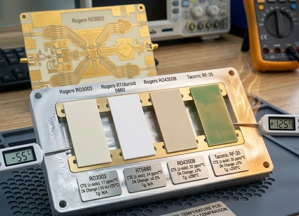
Thermal Cycling Reliability for Aerospace High Frequency PCB
Thermal cycling is the primary reliability stress mechanism for aerospace PCB. Each time the board cycles from cold to hot and back, the differential expansion between the copper conductors and the PCB laminate causes fatigue stress in the via barrels, solder joints, and copper traces. Over the life of the system, this fatigue accumulates and can lead to via barrel cracking and open circuits.
Thermal Cycling Test Standards
- IEC 60068-2-14: thermal shock testing — rapid transitions between temperature extremes
- MIL-STD-883 Method 1010: temperature cycling for military electronics
- IPC-TM-650 2.6.7.2: thermal cycling for PCB reliability qualification
- Typical aerospace qualification: 1000 cycles from -55°C to +125°C
- Accelerated testing may use wider range (-65°C to +150°C) to simulate longer service life in fewer cycles
Via Barrel Fatigue in Thermal Cycling
The most common thermal cycling failure mode in multilayer PCB is via barrel fatigue. The via barrel — the copper tube connecting layers through a drilled hole — is stressed by the differential expansion between the PCB laminate and the copper. In PTFE materials with high z-axis CTE, this stress is especially high.
- Thicker copper plating in via barrels improves fatigue life — IPC Class 3 minimum 25 µm
- Shorter via barrels (thinner boards) experience less absolute stress for the same CTE
- Copper fill in blind vias improves thermal cycling reliability by eliminating the void inside the via
- Via-in-pad designs with copper fill are more reliable than conventional vias in high thermal cycling applications
- Microsection analysis after thermal cycling reveals early-stage fatigue cracks before electrical failure
Design tip: For aerospace PCB requiring more than 1000 thermal cycles from -55°C to +125°C, specify copper-filled blind vias or thermal vias wherever possible, increase via barrel copper plating to 30 µm or above, and avoid boards thicker than 2.0 mm in pure PTFE stackups without engineering review of via fatigue life.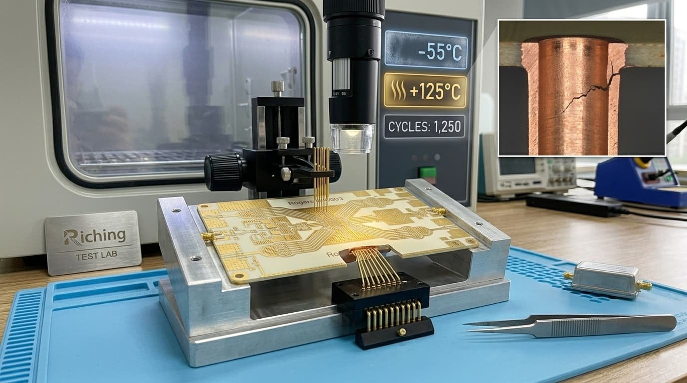
Controlled Impedance Stability Over Temperature
For high frequency PCB used in aerospace applications, the impedance of RF transmission lines must remain within specification across the full operating temperature range. Temperature affects impedance through two mechanisms: Dk variation and dimensional change.
Dk-Driven Impedance Shift
As Dk changes with temperature, the characteristic impedance of a microstrip or stripline changes. For a 50Ω microstrip on Rogers RO4350B, a Dk increase of 0.9% over the temperature range produces an impedance decrease of approximately 0.5%, or about 0.25Ω. For most applications this is within the ±10% production tolerance. For phase-sensitive systems like AESA phased arrays, this shift must be included in the worst-case analysis.
- RO3003 Dk temperature coefficient +13 ppm/°C: impedance variation over -55°C to +125°C ≈ 0.1%
- RO4350B Dk temperature coefficient +50 ppm/°C: impedance variation over same range ≈ 0.5%
- RT5880 Dk temperature coefficient -125 ppm/°C: impedance variation over same range ≈ 1.1% (opposite direction)
Dimensional-Driven Phase Shift
Physical dimensional change of the PCB with temperature affects the electrical length of transmission lines and antenna elements. For a 100 mm long transmission line on Rogers RO3003 (x-y CTE 17 ppm/°C), a 180°C temperature range causes approximately 0.31 mm of dimensional change — equivalent to approximately 0.3% change in electrical length at X-band. For AESA phased arrays, this phase error must be compensated electronically if it exceeds the beam steering budget.
For controlled impedance specifications and verification, see Why Controlled Impedance Matters in RF PCB Manufacturing.
Surface Finish for Wide Temperature Range Aerospace PCB
Surface finish selection for aerospace PCB operating over wide temperature ranges must consider solderability after temperature cycling, compatibility with conformal coating, and stability of the RF pad surface over the product lifetime.
- ENIG: most common for aerospace RF PCB — stable gold surface maintains solderability after temperature cycling and storage; flat surface for fine-pitch RF pads; compatible with conformal coating
- ENEPIG: preferred for wire bonding and highest reliability pads — eliminates ENIG black pad failure mode in applications with repeated thermal cycling
- Immersion silver: good RF surface performance but tarnish sensitivity requires careful handling and storage in aerospace environments
- OSP: not recommended for aerospace applications — limited thermal exposure and shelf life
- Hard gold: for edge connectors and contact areas subject to repeated mechanical engagement across temperature range
For surface finish comparison and specifications, see Surface Finish Options for RF and Microwave PCB.
Conformal Coating for Aerospace Wide Temperature Range PCB
Conformal coating is commonly applied to aerospace PCB to protect against humidity condensation, salt fog, fungal growth, and contamination at temperature extremes. The coating must remain flexible and adherent across the full operating temperature range without cracking or delaminating.
- Acrylic conformal coating: operating range typically -65°C to +125°C — most common for airborne electronics
- Silicone conformal coating: operating range typically -65°C to +200°C — best for highest temperature applications, lower dielectric loss
- Polyurethane conformal coating: operating range typically -55°C to +125°C — good chemical resistance
- Epoxy conformal coating: very high chemical resistance but less flexible — risk of cracking in wide thermal cycling
- Parylene conformal coating: excellent conformability and dielectric properties — used for highest reliability aerospace PCB
Note: Conformal coating must be kept off RF test points, connector pads, and any pad requiring soldering after coating. Selective coating application using liquid dispensing or spray masking must be specified on the assembly drawing. The coating material must be qualified for the specific temperature range and environmental exposure of the application.
Manufacturing Requirements for Wide Temperature Range Aerospace PCB
Manufacturing requirements for aerospace wide temperature range high frequency PCB go beyond standard commercial RF PCB production. The combination of PTFE materials, IPC Class 3, and thermal reliability requirements demands specific process controls.
PTFE Material Process Requirements
- Hole wall activation: sodium naphthalene or plasma etch before copper plating — essential for PTFE via reliability
- Maximum lamination cycles: 2 for PTFE materials — limits blind via complexity in PTFE-only stackups
- Drill parameters: specific spindle speed and feed rate for PTFE — standard FR4 parameters cause hole wall deformation
- Entry and exit materials: PTFE-compatible cover and backer boards for drilling
IPC Class 3 Requirements
- PTH copper plating: 25 µm average, 20 µm minimum at any point
- No annular ring breakout on any layer
- Maximum single void: 5% of hole length
- 100% electrical test: continuity and isolation for every board
- Microsection analysis for FAI and qualification
Thermal Qualification
- Thermal cycling qualification: 1000 cycles -55°C to +125°C for standard aerospace programs
- Microsection after thermal cycling: verifies via barrel integrity before electrical failure
- Delamination inspection: check for dielectric separation between layers after thermal cycling
- Electrical test before and after thermal cycling: confirms no resistance change in via chains
For IPC Class 3 requirements in detail, see IPC Class 3 High Frequency PCB: What It Means for Aerospace and Defense Applications. For PTFE process considerations, see PTFE PCB Manufacturing Challenges and Process Considerations.
Information Needed for Wide Temperature Range Aerospace PCB Quotation
To review feasibility and provide an accurate quotation for aerospace wide temperature range high frequency PCB, the following information should be prepared:
- Gerber files and NC drill files
- Complete PCB stackup with material specification, layer sequence, and copper weight
- Operating temperature range — minimum and maximum
- Storage temperature range
- Number of thermal cycles required over product life
- Thermal cycling test standard — IEC 60068-2-14, MIL-STD-883, or other
- Material specification — Rogers grade, PTFE type, or equivalent
- IPC Class requirement — Class 3 for aerospace
- Controlled impedance requirements with temperature stability requirement if applicable
- Via structure — through-hole, blind, buried, or copper-filled
- Conformal coating requirement — type, coverage area, and exclusion zones
- Surface finish and thickness specification
- Traceability and documentation requirements
- Applicable standards — MIL-PRF-31032, AS9100, or other
- Quantity — prototype or production lot
For a complete file checklist, see What Files Are Needed for a High Frequency PCB Quotation?.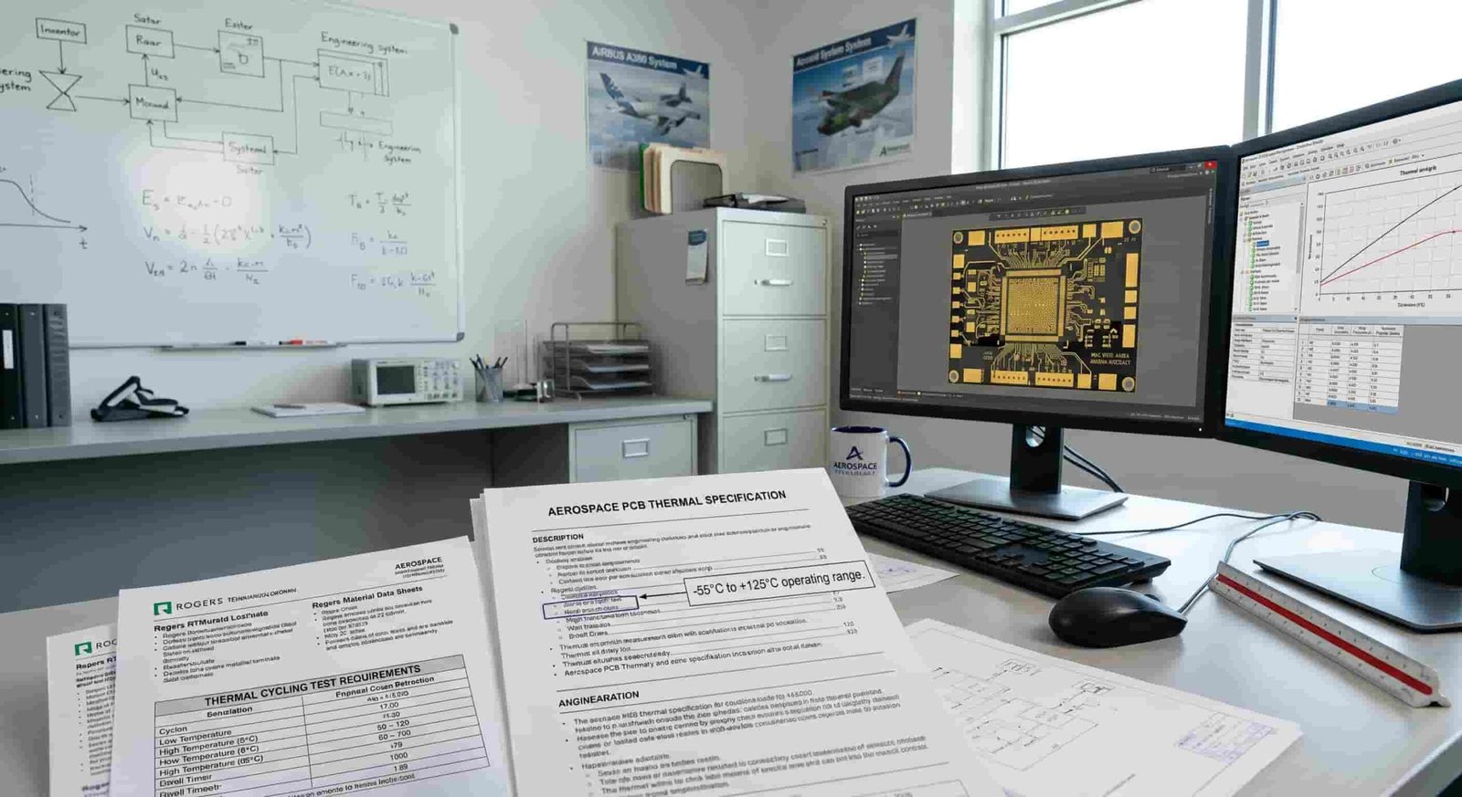
Conclusion
Wide temperature range performance for aerospace high frequency PCB requires materials that maintain stable Dk across the operating temperature range, provide CTE compatible with copper for long via fatigue life, and have Tg well above the maximum operating temperature. Rogers RO3003 provides the best balance of these properties for most aerospace applications. Rogers RT5880 is used where the lowest insertion loss is required despite its higher CTE. Rogers RO4350B offers a cost-effective option for applications not requiring the highest temperature stability.
IPC Class 3 workmanship, thermal cycling qualification, via reliability analysis, and full traceability documentation are standard requirements for high frequency PCB used in aerospace applications. Early material selection and stackup review with an experienced RF PCB manufacturer reduces thermal reliability risk and supports successful program qualification.