
MRI RF Coil PCB Material Selection — RO4350B vs RO3003 by Field Strength
The substrate material of an MRI RF coil PCB directly affects coil Q-factor, signal-to-noise ratio (SNR) and ultimately image quality. The wrong material choice at the design stage produces a coil that tests well on the bench but underperforms clinically — a problem that is expensive to fix after prototyping. This guide covers substrate selection by MRI field strength, from 1.5T clinical systems through 7T ultra-high field research.
Home » medical PCB material selection » MRI RF Coil PCB Material Selection — RO4350B vs RO3003 by Field Strength
Table of Contents
Why Substrate Df Affects MRI Coil Performance
An MRI RF coil is a resonant circuit — its quality factor (Q) determines how efficiently it converts RF energy into detectable signal. Q is reduced by any resistive loss in the circuit, including loss in the substrate dielectric. Dielectric loss is characterized by the dissipation factor (Df): higher Df means more energy absorbed by the substrate, lower Q, and reduced SNR.
The impact of substrate Df scales with frequency. At 64MHz (1.5T MRI), even FR4 (Df ~0.02) produces manageable substrate loss for simple coil geometries. At 298MHz (7T MRI), the same substrate loss is 4.7× higher in absolute terms — Rogers RO4350B (Df 0.0037) produces meaningful Q degradation, and Rogers RO3003 (Df 0.0010) becomes the correct material choice.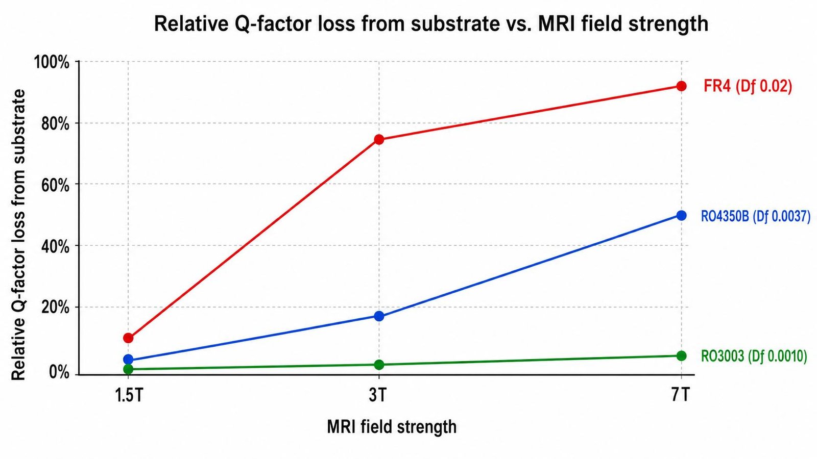
Material Comparison Table
| Material | Dk | Df | Best For |
|---|---|---|---|
| Rogers RO4350B | 3.48 | 0.0037 | 1.5T (64MHz) and 3T (128MHz) standard coils |
| Rogers RO4003C | 3.38 | 0.0027 | 3T coils where slightly lower Df is needed |
| Rogers RO3003 | 3.0 | 0.0010 | 7T (298MHz) ultra-high field — low Df critical |
| Rogers RT5880 | 2.20 | 0.0009 | Experimental UHF coils above 7T, loop antennas |
| FR4 standard | 4.3–4.6 | 0.02 | ❌ Not recommended — high loss, variable Dk |
Material Selection by Field Strength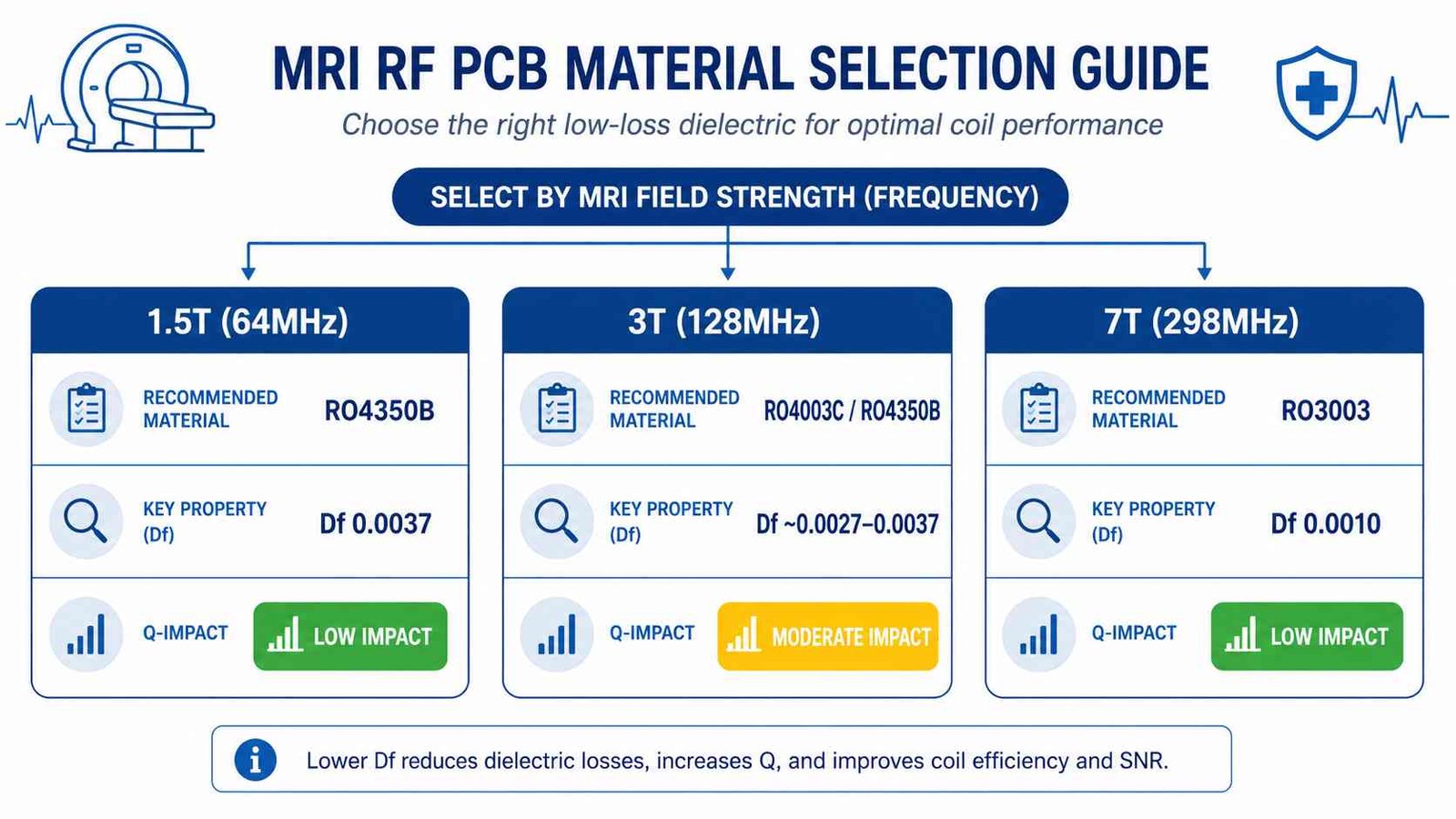
| MRI System | Field | Larmor Freq. | Recommended Material | Substrate Df Impact |
|---|---|---|---|---|
| Clinical 1.5T | 1.5T | 64 MHz | RO4350B | Low — Df 0.0037 acceptable at 64MHz |
| Clinical 3T | 3.0T | 128 MHz | RO4350B / RO4003C | Moderate — RO4003C preferred for high-Q designs |
| Research 7T | 7.0T | 298 MHz | RO3003 | High — RO4350B causes significant Q loss at 298MHz |
| UHF >7T | >7T | >298 MHz | RO3003 / RT5880 | Critical — lowest Df required |
1.5T MRI (64 MHz) — Rogers RO4350B
At 64MHz, substrate Df has relatively modest impact on coil Q. Rogers RO4350B (Df 0.0037) is the standard choice: it is a hydrocarbon ceramic material compatible with standard FR4-like fabrication processes, readily available, and produces adequate Q for clinical 1.5T surface coils, volume coils and phased arrays. The slightly higher Df of RO4350B vs RO3003 is not a significant performance differentiator at this frequency for most coil geometries.
3T MRI (128 MHz) — RO4350B or RO4003C
At 128MHz, substrate loss is approximately double that at 64MHz. RO4350B remains commonly used for 3T coil designs where coil geometry, sample loading and other loss mechanisms dominate the Q budget. For high-Q designs where substrate loss is a measurable contributor — particularly small-diameter coils with high unloaded-Q requirements — Rogers RO4003C (Df 0.0027) provides a modest improvement over RO4350B without the PTFE processing requirements of RO3003.
7T MRI (298 MHz) — Rogers RO3003
At 298MHz, substrate Df becomes a primary design constraint. Rogers RO4350B (Df 0.0037) produces substrate Q losses that are significant enough to affect image SNR in clinical and research applications. Rogers RO3003 (Df 0.0010) reduces substrate dielectric loss by approximately 3.7× compared to RO4350B at this frequency. For 7T coil development, RO3003 is the standard substrate choice.
RO3003 is a PTFE ceramic material and requires in-house plasma activation for reliable copper adhesion — a process step that most standard PCB manufacturers do not perform correctly. Verify your manufacturer’s PTFE process capability before ordering.
Additional Design Considerations
Trace geometry and copper weight
For loop coil designs, copper trace width and thickness affect conductor Q (separate from substrate Q). Thicker copper (2oz) reduces conductor resistance and improves unloaded Q, particularly for coils operating in the conductor-loss-limited regime. Specify copper weight on the stackup drawing.
Surface finish for MRI coils
ENIG (Electroless Nickel Immersion Gold) is the standard surface finish for MRI RF coil PCB. The flat, uniform surface maintains trace dimensional accuracy — critical for resonant frequency precision. HASL (tin-lead or lead-free) produces surface roughness that affects conductor Q and should be avoided for high-Q coil designs.
Biocompatibility and ISO13485
MRI RF coils that contact the patient require biocompatible surface finishes (ENIG or ENEPIG — no lead) and full material traceability under ISO13485 medical device quality management. For coils intended for clinical use or clinical trials, confirm your PCB manufacturer holds ISO13485 certification and can provide material lot records.
Quick Reference: Material by Application
- 5T surface coil, volume coil, phased array → RO4350B
- 3T surface coil (standard Q requirement) → RO4350B
- 3T surface coil (high Q, small diameter) → RO4003C
- 7T surface coil, volume coil → RO3003
- 7T+ experimental / UHF → RO3003 or RT5880
- Patient-contact coil (clinical) → ENIG or ENEPIG, ISO13485 manufacturer
Frequently Asked Questions — MRI RF Coil PCB Material
What PCB material is used for MRI RF coils?
Why does MRI coil PCB material matter?
Can FR4 be used for MRI RF coil PCB?
What surface finish should be used for MRI RF coil PCB?
Does MRI RF coil PCB require ISO13485 certification?
Need MRI RF Coil PCB Manufacturing?
ISO13485 certified. RO4350B and RO3003 in stock — no procurement delay for 1.5T, 3T and 7T coil prototypes. ENIG standard, full material traceability, IPC Class 3 on request.
Medical PCB Manufacturer → WhatsAppRequest a PCB Quote
Upload your Gerber ZIP file and project requirements. Our engineering team will review your PCB material, stackup, impedance needs, surface finish, and production quantity before quoting.
Please prepare:
- Gerber files in ZIP format
- PCB material or stackup requirements
- Controlled impedance notes if available
- Prototype or batch production quantity