PTFE PCB Lamination: 2-Cycle Limit, Bondply Selection and Hybrid Stackup Guide
Why PTFE is limited to 2 lamination press cycles, what happens when you exceed the limit, bondply options for PTFE/FR4 hybrid stackups, and multilayer PTFE stackup design rules.
Home » high frequency PCB stackup » PTFE PCB Lamination: 2-Cycle Limit, Bondply Selection and Hybrid Stackup Guide
Table of Contents
Key point: All PTFE materials are limited to a maximum of 2 lamination press cycles. Exceeding this shifts Dk across the panel and risks delamination. Hybrid PTFE + FR4 stackups require Rogers-specific bondply at every PTFE/FR4 interface — Rogers 4450F for RO4350B/RO4003C hybrids, Rogers 2929 for RO3003/RT5880 hybrids. Standard FR4 prepreg cannot be used at PTFE interfaces.
Most factories quote 3–4 weeks waiting for RO3003 / RT5880 material procurement. Riching PCB maintains these materials in stock with full bondply inventory — no material wait, 10–14 working day hybrid prototype.
PTFE PCB lamination has one rule that overrides all others: maximum 2 press cycles. Exceeding this limit causes irreversible PTFE deformation that shifts Dk across the panel and risks delamination at the PTFE/bondply interface. For single-material PTFE designs, the 2-cycle limit is straightforward to manage. For hybrid PTFE + FR4 stackups — where Rogers PTFE forms the outer signal layers and FR4 forms the inner power and ground planes — lamination planning becomes more complex and the bondply selection becomes critical.
This guide covers the 2-cycle limit and why it exists, bondply options for hybrid stackups, the two-stage lamination sequence for hybrid designs, and practical stackup design rules.
The 2 Press Cycle Limit Explained
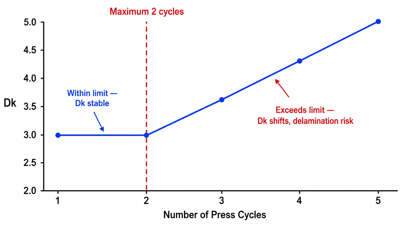
PTFE is a thermoplastic — it softens under heat and pressure. During lamination, the press cycle applies both. Within the first 2 cycles, the PTFE deforms slightly but recovers sufficiently that Dk and dimensional stability remain within specification. After the 2nd cycle, cumulative deformation causes:
- Dk variation across the panel — areas under higher pressure deform more, shifting local Dk
- Thickness variation — non-uniform PTFE compression produces dielectric thickness variation
- Delamination risk at bondply interfaces — repeated thermal cycling of the bondply adhesive reduces adhesion
- CTE mismatch fatigue — for hybrid stackups, repeated cycling accelerates fatigue at the PTFE/FR4 interface
The consequence for RF performance: Dk variation across the panel means impedance variation across the panel. For phased array designs where panel-level Dk uniformity is critical, exceeding the 2-cycle limit destroys the beam steering accuracy. For other RF designs, it introduces lot-to-lot impedance variation that cannot be corrected at TDR verification.
Bondply Selection for PTFE/FR4 Hybrid Stackups
| Bondply | Dk | Df | Use Case |
|---|---|---|---|
| Rogers 4450F | 3.52 | 0.004 | RO4350B / RO4003C to FR4 — most common hybrid bondply |
| Rogers 4450B | 3.54 | 0.004 | Alternative to 4450F — similar performance |
| Rogers 2929 | 2.94 | 0.003 | RO3003 / RT5880 to FR4 — PTFE-based bondply for PTFE outer layers |
| Rogers 4450T | 3.27 | 0.002 | Lower loss hybrid — Ku-band and above |
Bondply is the adhesive prepreg layer that bonds the PTFE outer layers to the FR4 inner core in a hybrid stackup. Standard FR4 prepreg cannot be used at the PTFE/FR4 interface — it does not have sufficient adhesion to PTFE and produces delamination under thermal cycling. Rogers-specific bondply materials are required.
Rogers 4450F — Most Common
Rogers 4450F is the standard bondply for RO4350B/RO4003C to FR4 hybrid stackups. It is a modified hydrocarbon ceramic prepreg that bonds to both RO4000 series Rogers materials and FR4 inner cores. Dk 3.52, Df 0.004 — similar to RO4350B, maintaining impedance continuity at the interface. Rogers 4450F is the most widely used bondply in commercial hybrid RF PCB production.
Rogers 2929 — For PTFE to FR4
Rogers 2929 is a PTFE-based bondply designed for bonding PTFE materials (RO3003, RT5880) to FR4 inner cores. It provides better adhesion to PTFE surfaces than 4450F and has lower Dk (2.94) and Df (0.003), reducing impedance discontinuity at the PTFE/FR4 interface. For Ka-band and mmWave hybrid stackups using RO3003 or RT5880 outer layers, Rogers 2929 is the recommended bondply.
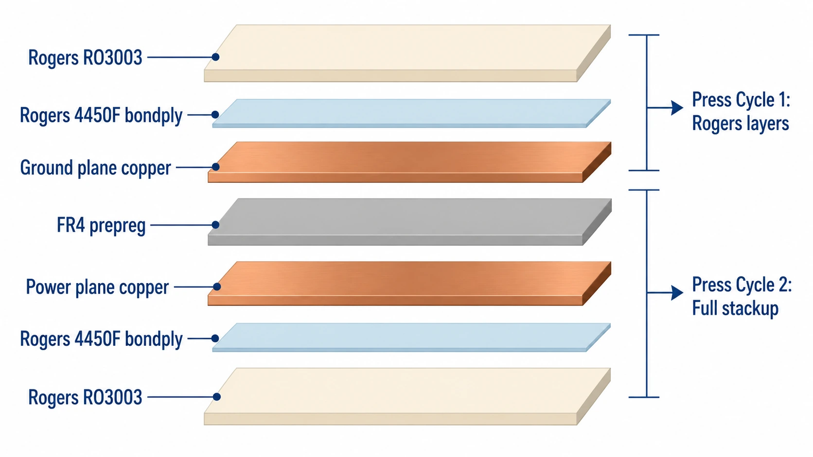
Two-Stage Lamination Sequence for Hybrid Stackups
A hybrid PTFE + FR4 stackup typically requires 2 press cycles — which exactly matches the PTFE limit:
- Press Cycle 1: FR4 inner core lamination — bond FR4 prepreg layers to inner copper layers to form the FR4 core subassembly
- Press Cycle 2: Full stackup lamination — bond Rogers PTFE outer layers to the FR4 core through bondply at the interfaces
This 2-cycle sequence uses the PTFE press cycle limit exactly. Any design requiring a 3rd press cycle — for example, adding blind vias or additional layer pairs — is not feasible with PTFE outer layers. Such designs must use RO4350B (hydrocarbon ceramic) instead of PTFE outer layers, as RO4350B has no press cycle limit.
Hybrid PTFE + FR4 Stackup Design Rules
| Layer | Material | Thickness | Purpose |
|---|---|---|---|
| L1 | RO4350B or RO3003 | 0.254 mm | RF signal — antenna, feed network |
| — | Rogers 4450F bondply | ~0.1 mm | PTFE-to-FR4 bond layer |
| L2 | Copper | 1 oz | Ground plane |
| — | FR4 prepreg | ~0.2 mm | Inner dielectric |
| L3 | Copper | 1 oz | Power plane |
| — | Rogers 4450F bondply | ~0.1 mm | FR4-to-PTFE bond layer |
| L4 | RO4350B or RO3003 | 0.254 mm | RF signal — or ground |
Rule 1: PTFE on outer layers only
PTFE layers must be outer layers in a hybrid stackup. PTFE as an inner layer requires 3+ press cycles — exceeding the limit. All practical hybrid PTFE + FR4 designs place Rogers PTFE on the outer RF signal layers and FR4 on the inner power and ground layers.
Rule 2: Bondply at every PTFE/FR4 interface
Every interface between a PTFE layer and an FR4 layer requires a compatible bondply. Do not substitute FR4 prepreg at PTFE interfaces. Specify bondply type (Rogers 4450F or Rogers 2929) explicitly on the stackup drawing — do not leave it to the fabricator to choose.
Rule 3: Confirm total stackup thickness
PTFE layers compress slightly under lamination pressure — more than FR4. The final board thickness may be 5–10% thinner than the sum of nominal layer thicknesses. Confirm the target board thickness with the fabricator before finalizing the stackup drawing, and specify a board thickness tolerance on the drawing.
Rule 4: Via design for hybrid stackups
Through-hole vias spanning both PTFE and FR4 layers experience CTE mismatch stress during thermal cycling — PTFE CTE (17–31 ppm/°C x/y) is significantly different from FR4 CTE (14–17 ppm/°C x/y). For high-reliability applications, use blind vias in the PTFE layer rather than through-hole vias spanning the full stackup. Confirm via design with the fabricator during DFM review.
All-PTFE vs Hybrid Stackup: When to Use Each
- All-PTFE (e.g. all-RO3003): use when uniformity of Dk across all layers is critical — phased arrays, wideband EW. Higher cost. Max 2 press cycles limits layer count.
- Hybrid PTFE + FR4: use when RF is only on outer layers and inner layers carry DC/power. 40–55% lower cost than all-PTFE. Same 2-cycle constraint on PTFE layers.
- All-RO4350B: use for designs below 12 GHz where PTFE is not required. No press cycle limit. Lowest cost Rogers option.
Conclusion
PTFE PCB lamination is limited to 2 press cycles — exceeding this shifts Dk across the panel and risks delamination. Hybrid PTFE + FR4 stackups require Rogers-specific bondply (4450F for RO4350B/RO4003C hybrids, 2929 for RO3003/RT5880 hybrids) and a 2-stage lamination sequence that uses the PTFE press cycle limit exactly. PTFE must be on outer layers only in hybrid designs. Riching PCB manufactures PTFE and hybrid RF PCB stackups with full bondply inventory — RO3003, RT5880 in stock, no material wait, 10–14 day hybrid prototype. See PTFE PCB manufacturing overview for the complete process guide.
Order PTFE or Hybrid RF PCB — Full Bondply Inventory
RO3003, RT5880 in stock. Rogers 4450F and 2929 bondply available. 10–14 day hybrid prototype.
- Gerber files + NC drill file
- Stackup drawing — specify bondply type at each PTFE/FR4 interface
- PTFE material grade and thickness
- Controlled impedance requirements
- IPC Class and quantity
WhatsApp +86 13760473650— DFM review within 24 hours
PTFE PCB Lamination Q&A
Common questions about the 2-cycle press limit, bondply selection, hybrid stackup design and lead times.
Why is PTFE PCB limited to 2 lamination press cycles?
PTFE deforms under heat and pressure. 1–2 cycles: acceptable deformation, Dk within spec. 3rd cycle: cumulative deformation shifts Dk across panel, thickness variation, delamination risk at bondply. Applies to all PTFE — RO3003, RT5880, Taconic, F4B.
What bondply is used for Rogers PTFE to FR4 hybrid stackups?
RO4350B/RO4003C to FR4: Rogers 4450F (Dk 3.52, Df 0.004). RO3003/RT5880 to FR4: Rogers 2929 (Dk 2.94, Df 0.003) — PTFE-based, better adhesion to PTFE surfaces. Standard FR4 prepreg cannot be used at PTFE interfaces.
How many press cycles does a PTFE + FR4 hybrid stackup require?
Exactly 2: Cycle 1 laminates FR4 inner core. Cycle 2 bonds PTFE outer layers to FR4 core through bondply. Uses the PTFE limit exactly. Any design needing a 3rd cycle is not feasible with PTFE outer layers.
Can PTFE be used as an inner layer?
No — inner PTFE layer would require 3+ cycles, exceeding the limit. PTFE must be outer layer(s) only. FR4 forms the inner core. This ensures PTFE is only exposed to 1 press cycle (the final full-stackup lamination).
What is the lead time for PTFE + FR4 hybrid PCB prototype?
10–14 working days — 2-stage lamination sequence. Rogers 4450F and 2929 bondply in stock. RO3003 and RT5880 in stock — no material wait. No MOQ. WhatsApp: +86 13760473650.
Request a PCB Quote
Upload your Gerber ZIP file and project requirements. Our engineering team will review your PCB material, stackup, impedance needs, surface finish, and production quantity before quoting.
Please prepare:
- Gerber files in ZIP format
- PCB material or stackup requirements
- Controlled impedance notes if available
- Prototype or batch production quantity
