PTFE PCB and FR4 PCB are often compared when a design moves from standard electronics into RF, microwave, antenna, radar, or other high frequency applications. FR4 is widely used, cost-effective, and easy to process. PTFE-based materials are usually reviewed when the circuit needs lower signal loss, more stable dielectric behavior, or better high frequency performance.
The right choice is not based on material name alone. A simple control board may work well on FR4. A microwave signal path, antenna feed network, or low-loss RF transmission line may need PTFE or another high frequency laminate.
For buyers, the decision should be based on working frequency, signal loss target, impedance control, stackup, manufacturing difficulty, cost, and repeat production needs.
Quick Summary
FR4 is suitable for many standard PCB applications and some lower-frequency RF sections when signal loss is not strict.
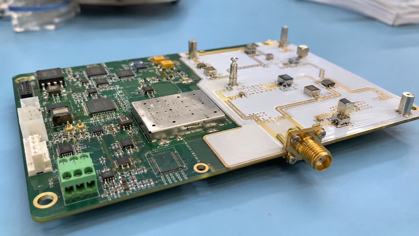
PTFE PCB is often used for microwave circuits, antenna systems, radar electronics, satellite communication, RF test boards, and low-loss high frequency signal paths.
The main differences include dielectric loss, Dk stability, manufacturing difficulty, drilling and plating behavior, dimensional control, and total project cost.
FR4 should not be selected only because it is cheaper. PTFE should not be selected only because it sounds higher performance. The material should match the real RF requirement.
Why FR4 Is Still Widely Used
FR4 remains the most common PCB material because it is practical, available, and familiar to almost every PCB factory.
It is often used for:
Control circuits
Power management sections
Digital circuits
General industrial electronics
Low-speed signal boards
Some lower-frequency RF designs
Support layers in hybrid stackups
For many projects, FR4 is the right choice. It helps control cost and lead time. It also supports mature drilling, plating, lamination, and assembly processes governed by standard IPC manufacturing guidelines.
The problem starts when FR4 is used in a circuit that needs low-loss and stable high frequency performance. At higher frequencies, dielectric loss and material variation become more visible.
When FR4 May Not Be Enough
FR4 may become risky when the circuit includes long RF paths, microwave traces, antenna feed lines, radar signals, or strict impedance control.
Warning signs include:
Higher working frequency
Long controlled impedance traces
Low insertion loss requirement
Sensitive antenna tuning
Microwave connector transitions
High repeatability requirement
Strict RF test standard
Prototype-to-batch performance concern
In these cases, FR4 may still be easy to fabricate, but the finished board may not meet signal performance expectations.
A board can pass visual inspection and still fail RF testing. That is why high frequency material selection should be reviewed before layout and production.
Why PTFE PCB Is Used
PTFE-based PCB materials are often selected when the design needs low dielectric loss and stable microwave performance.
Typical applications include:
Radar PCBs
Satellite communication circuits
Antenna feed networks
RF test fixtures
Aerospace RF boards
Low-loss signal transmission lines
High frequency filters
PTFE materials can help reduce dielectric loss and support more stable RF behavior. However, they also bring more manufacturing challenges compared with standard FR4.
This means PTFE is not simply a “better FR4.” It is a different material system that requires proper process control.
Signal Loss Difference
Signal loss is one of the main reasons to compare PTFE PCB and FR4 PCB.
At lower frequencies, FR4 may be acceptable if the trace is short and the performance requirement is not strict. As frequency increases, FR4 loss can become more noticeable. PTFE-based materials are usually reviewed when lower loss is needed.
However, material is only one part of loss control.
Signal loss also depends on:
Trace length
Copper roughness
Dielectric thickness
Surface finish
Connector launch
Via transitions
Ground reference
Manufacturing tolerance
A PTFE material will not fix a poor RF layout. If the connector area, via transition, or ground plane is poorly designed, the board can still perform badly.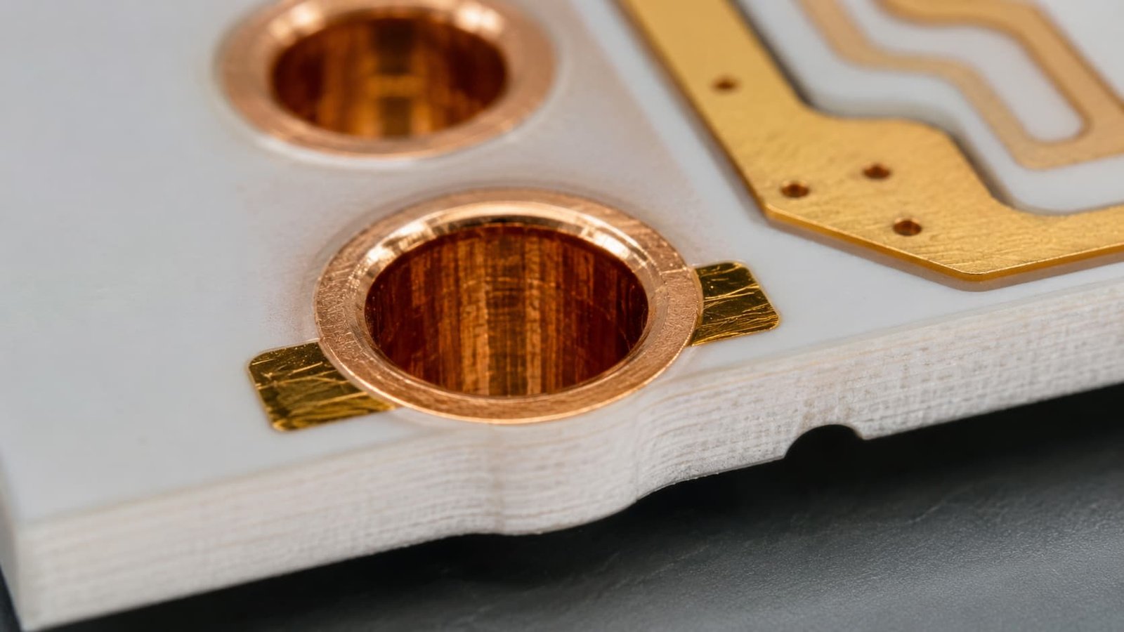
Controlled Impedance Review
Both FR4 and PTFE PCB can be used in controlled impedance designs, but the material behavior is different.
Controlled impedance depends on:
Dk value
Dielectric thickness
Trace width
Copper thickness
Ground reference
Solder mask condition
Etching tolerance
Final production stackup
For FR4, material variation may be acceptable in many standard circuits. For RF and microwave circuits, this variation can create more risk. PTFE-based materials are often reviewed when the design needs more stable dielectric behavior.
Before production, the manufacturer should confirm the real stackup and calculate impedance based on production material, not only the design assumption.
Manufacturing Difficulty
FR4 is easier to process. Most PCB factories are familiar with its drilling, plating, lamination, etching, and surface finish behavior.
PTFE PCB usually requires more careful manufacturing control.
Key process points include:
Drilling quality
Hole wall preparation
Plated through-hole reliability
Copper adhesion
Dimensional stability
Material handling
Lamination behavior
Etching control
Surface finish selection
PTFE materials can be softer or more difficult to process than FR4. If the manufacturer does not have experience with PTFE processing, the material advantage may be lost during fabrication.
Hybrid Stackups
Some designs do not need the whole board to use PTFE.
A practical option is a hybrid stackup, where high frequency material is used only for RF or microwave signal layers, while FR4 is used for control, power, or mechanical support sections.
Hybrid stackups may help balance:
RF performance
Material cost
Board thickness
Mechanical strength
Layer count
Manufacturing feasibility
Batch production cost
However, hybrid boards still need careful review. Different materials may behave differently during lamination, drilling, and thermal stress. The stackup should be confirmed before production.
Cost and Procurement Review
FR4 is usually lower cost and easier to source. PTFE materials are usually more expensive and may require longer lead time or special processing.
But procurement should not compare only material price.
The real project cost includes:
Prototype success rate
RF testing risk
Material availability
Manufacturing yield
Impedance testing
Rework or redesign risk
Batch repeatability
Lead time stability
A cheaper FR4 board may become expensive if it fails RF testing. A PTFE board may also become expensive if it is selected without confirming manufacturing feasibility.
The best material is the one that meets the RF requirement with acceptable production risk.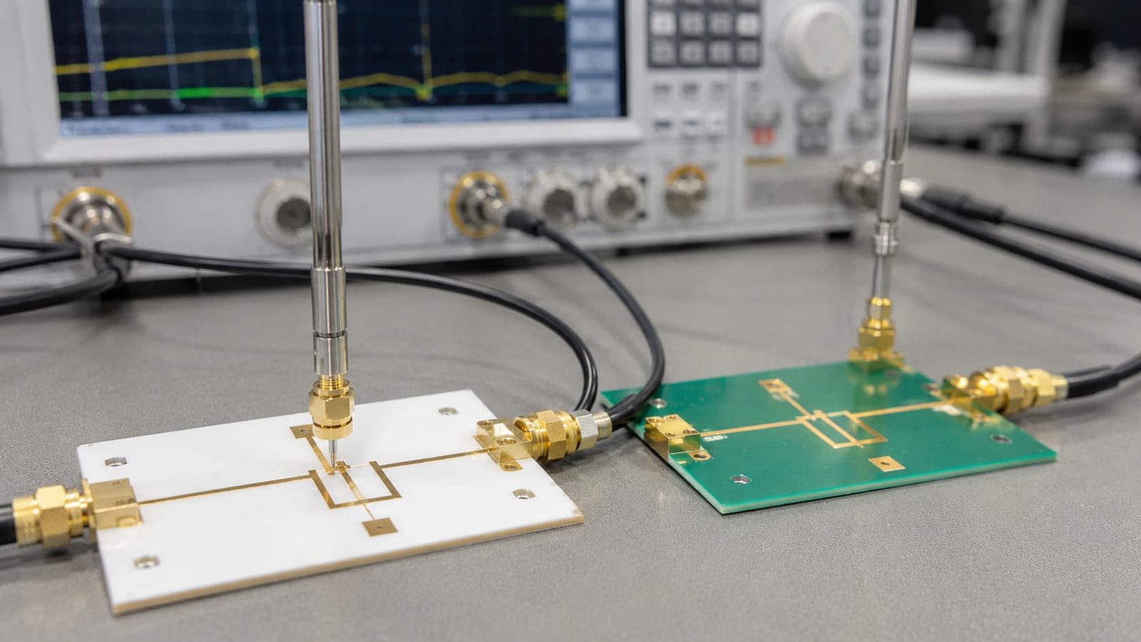
What Buyers Should Provide for Quotation
To compare PTFE PCB and FR4 PCB properly, buyers should prepare:
Gerber files
Drill files
PCB stackup
Material preference
Working frequency
Controlled impedance requirement
Signal loss requirement if available
Board thickness
Copper thickness
Surface finish
Quantity
Prototype or batch plan
Application background
If the buyer is not sure whether FR4 is enough, the working frequency and signal path information are especially useful. The manufacturer can then review whether FR4, PTFE, or a hybrid structure is more reasonable.
Common Mistakes to Avoid
Common mistakes include:
Using FR4 only because it is cheaper
Choosing PTFE without checking manufacturing difficulty
Changing material after layout
Sending files without stackup
Ignoring dielectric thickness
No controlled impedance table
Ignoring drilling and plated hole risk
Using the same material for all board sections without review
Not considering batch material availability
Comparing material cost instead of total project risk
These issues may not appear during visual inspection. They often appear during RF testing, assembly, or repeat production.
Conclusion
FR4 PCB is practical, cost-effective, and reliable for many standard electronics and some lower-frequency RF applications. PTFE PCB is often reviewed when the project needs lower loss, stable dielectric behavior, and stronger high frequency performance.
FR4 is not enough when the signal path becomes sensitive to dielectric loss, impedance shift, antenna tuning, or microwave behavior. PTFE can solve some of these problems, but only when the design, stackup, drilling, plating, and manufacturing process are reviewed properly.
For buyers, the safest decision is to compare PTFE PCB and FR4 PCB by working frequency, signal loss, impedance, stackup, manufacturing difficulty, availability, and production risk — not only by price.