
5G/IoT Terminal Antenna PCB Checklist — What to Review Before SAR Certification
Automated SAR test platforms are compressing the time between a design freeze and a certification result, which leaves less room for antenna, grounding, and placement problems to surface on the PCB before tooling is committed. This checklist covers the PCB-level items worth reviewing before a 5G or IoT terminal goes into SAR testing: antenna keepout, ground return continuity, module placement, and multi-transmitter isolation.
Home » 5G/IoT Terminal Antenna PCB Checklist — Before SAR Certification Testing
Table of Contents
Automated SAR (Specific Absorption Rate) test workflows now link fast measurement software, vector array systems, and signaling test sets into a single interface, cutting manual setup time and improving repeatability for 5G NR and LTE terminal certification. That kind of automation is good news for test throughput, but it also means a terminal reaches certification testing faster — and a PCB-level issue with antenna matching, ground plane, power control, or enclosure coupling gets discovered later in the schedule than it used to, at a point where a board respin is expensive.
For a board house working with 5G and IoT terminal customers, that shift is an opening: a DFM review focused specifically on the items that drive SAR results, done before the design is frozen, catches problems while they’re still cheap to fix.
Why SAR Results Trace Back to the PCB
SAR measures how much RF energy a device’s antenna couples into simulated body tissue at a defined distance and power level. Everything that shapes the antenna’s radiated field and the device’s actual transmit power in that configuration — antenna matching, ground plane continuity, enclosure coupling, and how accurately the radio’s power control tracks its intended output — has a PCB-level origin. A layout that looks electrically fine on a bench VNA sweep can still produce a SAR result that’s higher than expected if the near-field behavior around the antenna doesn’t match what the RF design assumed.
Antenna Keepout and Placement for SAR
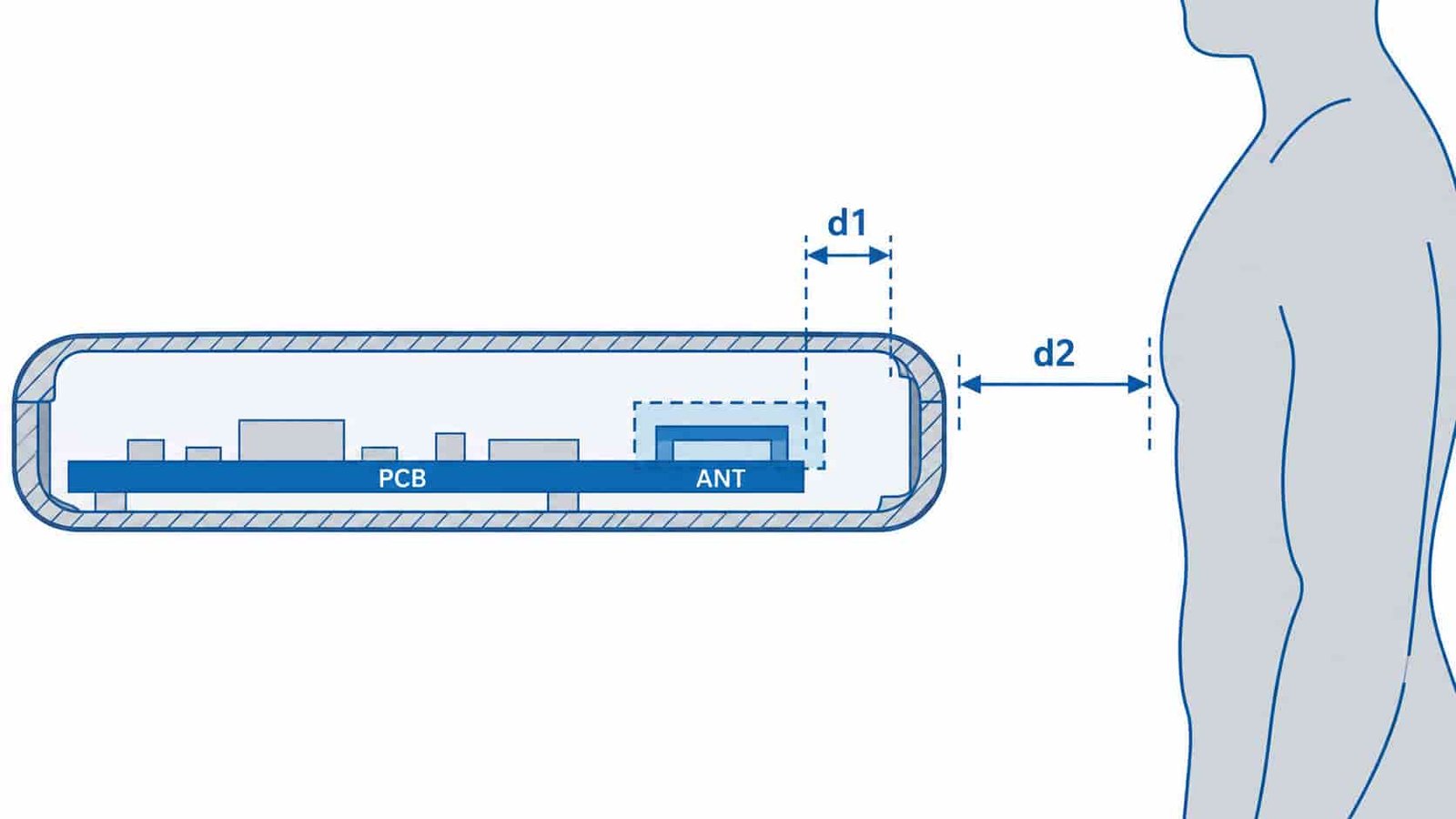
Antenna keepout zones matter for radiated performance on any RF board, but for SAR specifically, the keepout also has to account for the antenna’s proximity to the body-proximity test position, not just to the nearest metal enclosure feature. Placement decisions that are perfectly acceptable for link performance — moving an antenna slightly to fit a battery outline, for example — can shift how much of the radiated field couples toward the body-worn or hand-held test configuration.
The same keepout-zone discipline covered in our UWB positioning module PCB design guide applies here, extended to the specific geometry a SAR test configuration assumes rather than just the antenna vendor’s general clearance recommendation.
Ground Return Path and Ground Plane Continuity
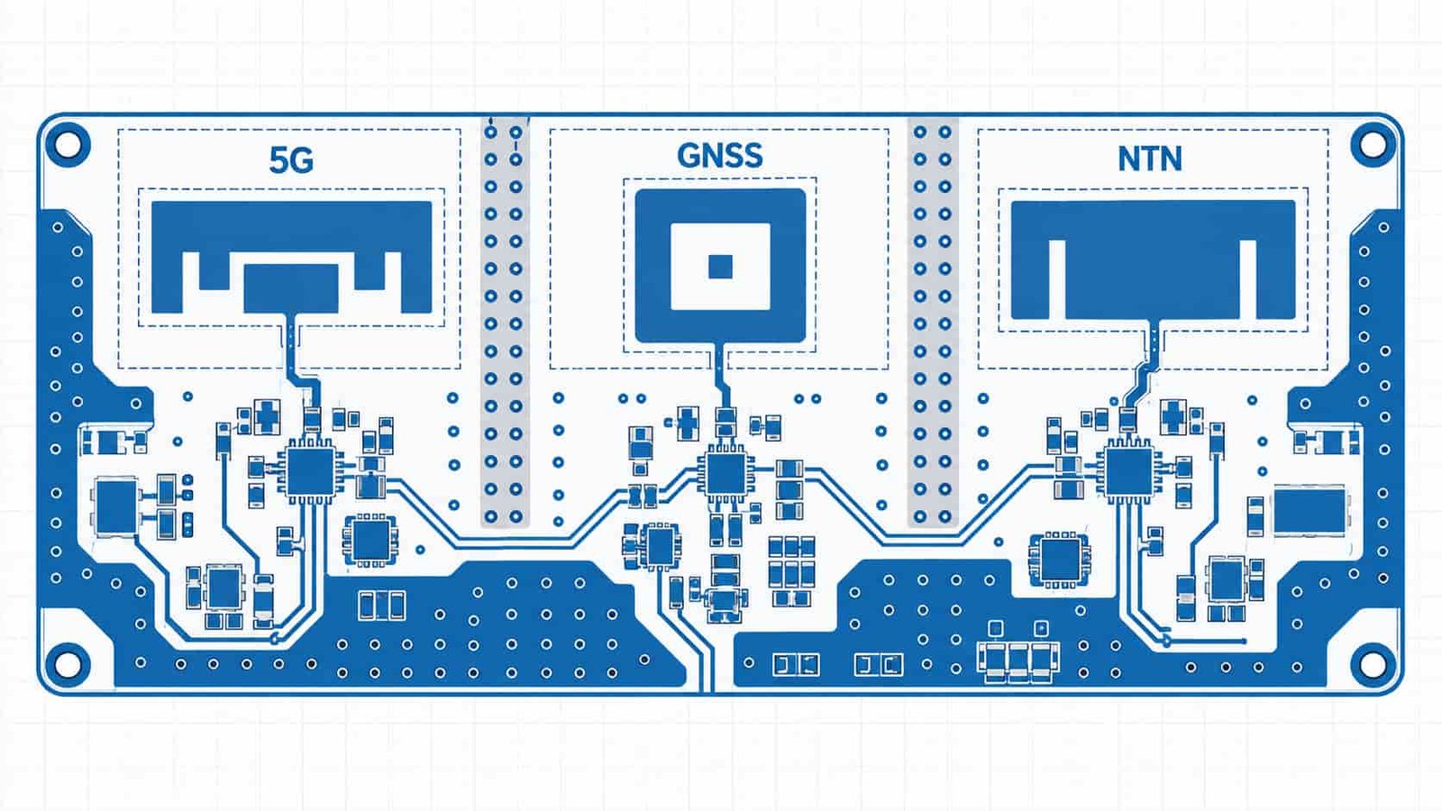
A discontinuous or poorly stitched ground plane near an antenna feed changes the antenna’s effective radiating structure, sometimes in ways that don’t show up as an obvious mismatch on a bench measurement but do shift the far-field and near-field pattern that SAR testing evaluates. Reviewing ground plane continuity specifically around every antenna feed — not just the primary cellular antenna — is worth doing as a dedicated check, since GNSS and NTN antenna zones are easy to treat as an afterthought during layout.
Module Placement and Board-Edge Copper
Where an RF module sits relative to the enclosure edge, and how much copper is left at the board edge near an antenna, both influence how the radiated field couples to nearby metal structures in the finished device. A module placed to solve a mechanical or thermal constraint late in the design can end up closer to a metal frame or battery than the original RF layout assumed, and that kind of late-stage placement change is exactly the sort of item a pre-certification DFM pass is meant to catch.
| Check Item | What to Verify | Why It Matters | Typical Failure Mode |
|---|---|---|---|
| Antenna keepout zone | Clearance matches the actual body-proximity test configuration | Shapes near-field coupling that SAR directly measures | Keepout shrunk to fit a battery/mechanical constraint late in layout |
| Ground plane continuity | No gaps or splits near any antenna feed, incl. GNSS/NTN | Changes effective radiating structure and field pattern | Secondary antennas treated as an afterthought during routing |
| Module placement | Checked against final mechanical assembly, not reference layout | Proximity to metal frame/battery affects field coupling | Module moved late for thermal/mechanical reasons |
| Board-edge copper | Clearance from antenna to nearest board-edge copper fill | Couples to nearby enclosure metal structures | Copper pour extended to board edge without RF review |
| Multi-transmitter isolation | Physical separation + shielding between 5G/GNSS/NTN zones | Simultaneous transmission can add to total exposure | Each radio passed standalone but not in combination |
| Power control accuracy | RF front-end layout supports accurate power ramp/control | SAR partly reflects actual vs. intended transmit power | Control line routing/parasitics affecting ramp accuracy |
| Certification pathway | Confirm SAR vs. other exposure standard for the use case | Body-proximity vs. fixed-mount automotive differ | Wrong checklist applied for the product's actual use case |
Multi-Transmitter Isolation
Terminals that combine 5G, GNSS, and non-terrestrial network (NTN) radios on one board raise a specific SAR consideration: simultaneous transmission from multiple radios can add to the total RF exposure the test configuration measures, not just to interference between the radios. Physical separation between antenna zones, ground-stitched shielding rows between them, and confirming which transmit combinations are actually tested together are all worth reviewing explicitly rather than assuming isolation is adequate because each radio passed its own standalone test.
The RF/digital isolation principles covered in our guide to RF and digital mixed-signal PCB stackup design apply to isolating one RF section from another on the same board, not only to isolating RF from a digital control bus.
Automated SAR testing finds problems faster, but it doesn’t make a late-stage PCB fix any cheaper. An antenna keepout violation or a ground plane gap discovered after tooling is committed still means a board respin and a schedule slip — the value of automation is in catching that at the DFM review stage, before the design is frozen, not in reacting faster after certification fails.
Where This Fits for Automotive and Industrial Programs
A 5G/NTN module built for an automotive telematics unit or ADAS platform carries the same antenna and isolation review needs described here, on top of the traceability and batch-consistency requirements already familiar from automotive radar PCB programs. Confirming which certification requirements apply — SAR for a body-proximity use case, or a different exposure standard for a fixed-mount automotive application — is worth doing early, since it changes which checklist items actually matter for a given design.
A Pre-Certification DFM Checklist
Reviewing these items before a design is frozen, rather than after a SAR test result comes back high, is the difference between a layout tweak and a respin:
- Antenna keepout validated against the actual body-proximity test configuration, not just general RF clearance guidance.
- Ground plane continuity confirmed around every antenna feed, including GNSS and NTN, not only the primary cellular antenna.
- Module and board-edge copper placement checked against the final mechanical assembly, not an earlier reference layout.
- Isolation between simultaneously transmitting radios verified for the actual transmit combinations the device will use.
5G/IoT Terminal Antenna PCB Checklist — Q&A
Common questions on antenna keepout, grounding, and isolation before SAR certification testing.
Why does an automated SAR test failure often trace back to a PCB layout issue?
SAR measures RF coupling into simulated body tissue, and antenna matching, ground plane continuity, enclosure proximity, and power control accuracy all originate in the PCB layout. A board can look fine on a bench VNA sweep and still produce a high SAR result if its near-field behavior doesn't match the RF design's assumptions.
What antenna keepout considerations are specific to SAR compliance versus general RF performance?
General RF keepout focuses on clearance from enclosure metal and nearby components. SAR-specific keepout also has to account for proximity to the body-proximity test position, since that geometry directly shapes the measured exposure.
Why does simultaneous multi-transmitter operation (5G + GNSS + NTN) matter for SAR?
Transmitting multiple radios at once can add to total measured exposure, not just create interference. A radio that passes standalone testing may still need separate verification in its actual simultaneous-transmit combinations.
When in the design cycle should a SAR-focused PCB DFM review happen?
Before the design freeze and mechanical tooling commitment. Automated SAR platforms test faster, but a fix found after tooling is locked still means a respin — reviewing antenna and grounding items at the DFM stage is where that speed actually helps.
Need a Pre-Certification Antenna PCB Review?
We support 5G/IoT terminal and automotive telematics programs with antenna keepout, grounding, and multi-transmitter isolation DFM reviews before SAR certification — plus quick-turn layout fixes when issues turn up.
Contact Us → WhatsAppRequest a PCB Quote
Upload your Gerber ZIP file and project requirements. Our engineering team will review your PCB material, stackup, impedance needs, surface finish, and production quantity before quoting.
Please prepare:
- Gerber files in ZIP format
- PCB material or stackup requirements
- Controlled impedance notes if available
- Prototype or batch production quantity