Aerospace and defense electronics operate in environments that push the limits of conventional PCB technology. Airborne radar systems, electronic warfare equipment, satellite communication modules, missile guidance electronics, and avionics systems all rely on high frequency PCB that must perform reliably across extreme temperature ranges, withstand mechanical shock and vibration, maintain signal integrity at microwave and millimeter-wave frequencies, and meet strict quality and traceability requirements.
Standard commercial high frequency PCB materials and processes are often insufficient for aerospace and defense applications. The combination of frequency, temperature range, reliability class, and lifetime requirements means that material selection, stackup design, manufacturing process control, and quality documentation must all be reviewed at a higher standard than commercial RF PCB production.
This guide covers the key material, reliability, and manufacturing requirements for high frequency PCB used in aerospace and defense applications, and what buyers and engineers should confirm before production.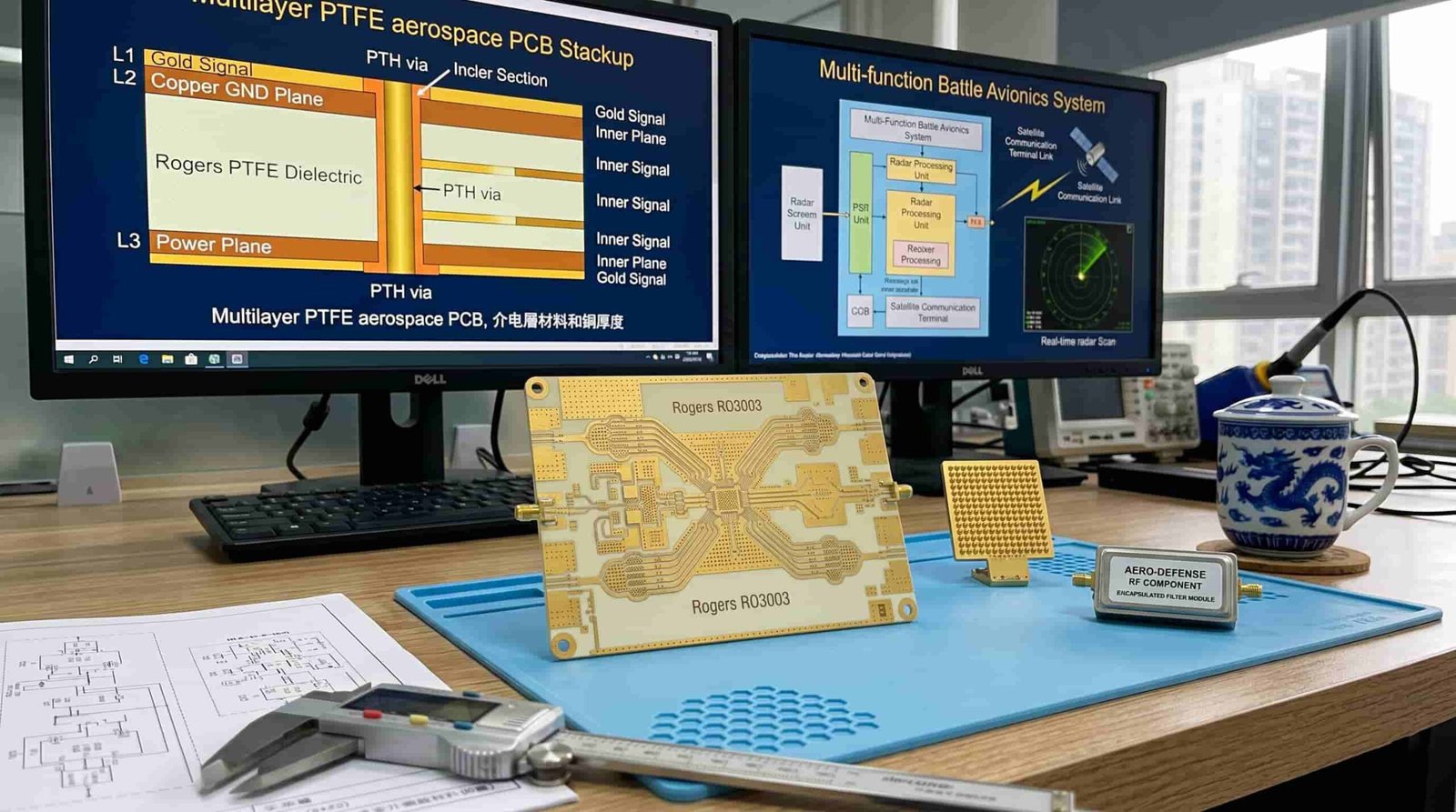
Quick Summary
Key point: Aerospace and defense high frequency PCB typically requires Rogers RO4350B, RO3003, RT5880, or equivalent PTFE materials, IPC Class 3 workmanship, wide temperature range from -55°C to +125°C or beyond, controlled impedance ±10% or tighter, full traceability documentation, and qualification to relevant military or aerospace standards. Material lot certification, first article inspection, and serialized traceability are commonly required.
The most important difference between commercial RF PCB and aerospace defense PCB is not the material alone — it is the combination of material performance, process control, inspection depth, and documentation. A Rogers RO3003 board built to IPC Class 2 and a Rogers RO3003 board built to IPC Class 3 with full traceability are very different products even if the schematic and layout are identical.
Why Aerospace and Defense High Frequency PCB Is Different
Aerospace and defense electronics impose requirements that go beyond what commercial high frequency PCB production typically addresses. Understanding these differences helps engineers specify boards correctly and helps buyers ask the right questions when evaluating suppliers.
Operating Environment
Commercial RF PCB typically operates at room temperature or in climate-controlled environments. Aerospace and defense electronics may be exposed to:
- Temperature range: -55°C to +125°C for airborne electronics, wider for space applications
- Altitude: reduced air pressure affects thermal management and corona discharge margins
- Humidity: condensation, salt fog, and fungal growth in tropical and maritime environments
- Vibration and shock: aircraft vibration profiles, launch loads for space, gun-fire shock for military
- Radiation: ionizing radiation in space and high-altitude applications
Reliability Class
IPC-A-600 and IPC-6012 define three classes of PCB acceptability. Class 3 applies to high reliability electronics where continued performance is critical and equipment failure is not an acceptable outcome. Most aerospace and defense high frequency PCB is specified to IPC Class 3.
- Class 1: general electronics — basic functional requirements
- Class 2: dedicated service electronics — extended life, uninterrupted service
- Class 3: high reliability — continued performance, no failure tolerance — aerospace, defense, medical
Lifetime and Maintenance
Commercial electronics may be replaced every few years. Aerospace and defense systems often have 20–30 year service lives with limited maintenance access. The PCB must maintain electrical performance and mechanical integrity throughout this lifetime without degradation.
Traceability and Documentation
Aerospace and defense supply chains require full traceability from raw material to finished board. This includes material certificates, laminate lot numbers, process records, inspection data, and test results — all linked to specific serialized boards or panel lots.
Material Selection for Aerospace and Defense High Frequency PCB
Material selection for aerospace and defense high frequency PCB must balance electrical performance at the operating frequency, thermal stability across the operating temperature range, mechanical properties for vibration and shock resistance, and compatibility with the required manufacturing process and quality class.
Rogers RO4350B — Most Common for Airborne RF
Rogers RO4350B is the most widely used material for airborne and defense RF PCB operating up to approximately 30–40 GHz. Its hydrocarbon ceramic base provides stable Dk of 3.48 ±0.05, Df of 0.0037 at 10 GHz, and compatibility with standard multilayer lamination processes. Its Tg of >280°C and thermal conductivity of 0.69 W/m·K make it suitable for most airborne electronics environments.
- Dk: 3.48 ±0.05 — consistent across production lots
- Df: 0.0037 at 10 GHz — suitable for most airborne radar and communication frequencies
- Tg: >280°C — excellent thermal stability
- CTE (z-axis): 32–46 ppm/°C — must be considered for thick boards with many thermal cycles
- Compatible with standard FR4 multilayer lamination — supports hybrid stackups
- Lead-free solder compatible
Rogers RO3003 — For Higher Frequency and Lower Loss
Rogers RO3003 is used for defense applications requiring lower insertion loss or operating frequencies above 30 GHz, including ground-based radar, airborne radar at W-band, and millimeter-wave electronic warfare systems. Its PTFE base provides Dk of 3.0, Df of 0.0010, and excellent dimensional stability over temperature with CTE of 17 ppm/°C.
- Dk: 3.0 ±0.04 — very stable across temperature and frequency
- Df: 0.0010 — low loss for frequencies above 30 GHz
- CTE (x-y): 17 ppm/°C — close to copper, good for large multilayer boards
- PTFE base — requires special process for hole wall activation before plating
- Limited to 2 lamination cycles — constrains blind via complexity
Rogers RT5880 — Ultra-Low Loss for EW and mmWave
Rogers RT5880 offers the lowest Dk (2.2) and Df (0.0009) of widely used defense PCB materials, making it the choice for electronic warfare systems, phased array radar, millimeter-wave sensors, and low-probability-of-intercept (LPI) radar applications where insertion loss must be minimized.
- Dk: 2.2 ±0.02 — lowest of commonly used defense laminates
- Df: 0.0009 at 10 GHz — ultra-low loss for EW and mmWave applications
- Available in thin substrates: 0.127 mm to 3.175 mm
- PTFE base — requires sodium or plasma activation before plating
Hybrid FR4 + Rogers Stackups
For defense PCB where RF performance is required only on certain layers and cost or weight must be managed, hybrid stackups combining Rogers or PTFE material on RF layers with FR4 on digital and power layers are commonly used.
For hybrid stackup design details, see FR4 + Rogers Hybrid PCB Stackup: When Should You Use It?.
IPC Class 3 Requirements for Aerospace Defense High Frequency PCB
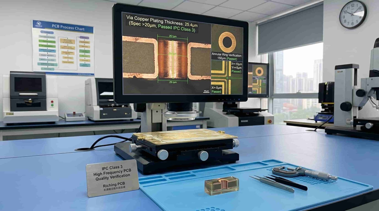
IPC Class 3 is the workmanship and acceptability standard for high reliability PCB. For aerospace and defense high frequency PCB, Class 3 requirements apply to hole wall copper plating, annular ring, surface finish, dielectric integrity, and conductor quality.
Key IPC Class 3 Requirements for High Frequency PCB
- Minimum copper plating in PTH holes: 25 µm average, 20 µm minimum at any point (vs 20 µm average for Class 2)
- Minimum annular ring: 50 µm for internal layers, no breakout allowed
- Maximum void in plated holes: no voids greater than 5% of hole length in any single void
- Dielectric layer integrity: no delamination, measling, or weave exposure
- Surface finish: must meet Class 3 solderability and thickness requirements
- Conductor definition: no nicks, pinholes, or rough edges that reduce conductor width below minimum
First Article Inspection (FAI)
For defense and aerospace programs, first article inspection (FAI) is commonly required. FAI verifies that the manufacturing process produces boards that meet all design and specification requirements before full production begins. This typically includes microsection analysis, dimensional verification, electrical testing, and documentation review.
Traceability Requirements
- Material certificates for all laminates, prepregs, and surface finish chemicals
- Laminate lot number recorded and linked to each production lot
- Process traveler documenting each manufacturing step with operator identification
- AOI and electrical test records for each panel
- Serialization or lot coding on each board or panel
- Material and process records retained for the program lifetime — typically 10–30 years
Thermal and Mechanical Reliability for Aerospace Defense PCB
Wide Temperature Range Performance
Aerospace and defense electronics must maintain electrical performance across wide temperature ranges. The PCB material, surface finish, and solder joint must all survive repeated thermal cycling without cracking, delamination, or electrical degradation.
- Typical airborne electronics: -55°C to +125°C operating, -65°C to +150°C storage
- Space applications: -100°C to +150°C or wider depending on orbit and shielding
- Thermal cycling test: typically 1000 cycles from -55°C to +125°C for Class 3 qualification
- Rogers PTFE materials (RO3003, RT5880) have excellent Tg — no glass transition in operating range
- Rogers RO4350B Tg > 280°C — well above any airborne operating temperature
Vibration and Shock
Airborne and military electronics must survive vibration and shock levels defined by MIL-STD-810 or equivalent standards. PCB design must account for component mass and board resonant frequency. Heavier components on high layer count boards in vibration-intensive applications may require staking, underfill, or conformal coating.
- MIL-STD-810 Method 514.8: vibration testing for military electronics
- MIL-STD-810 Method 516.8: shock testing
- PCB natural frequency should be kept above the excitation frequency range where possible
- Conformal coating protects against humidity, fungal growth, and contamination in harsh environments
Conformal Coating Compatibility
Many aerospace and defense PCB require conformal coating after assembly. The surface finish and solder mask must be compatible with the coating material (acrylic, silicone, polyurethane, or epoxy). ENIG and ENEPIG surface finishes are generally compatible with all common conformal coating types.
Controlled Impedance in Aerospace Defense High Frequency PCB
Controlled impedance is a standard requirement for RF signal traces in aerospace and defense PCB. The impedance target, tolerance, and verification method must be specified on the fabrication drawing.
- Standard impedance tolerance: ±10% for traces ≥ 50Ω
- Tighter tolerance: ±5% or ±3Ω may be specified for critical phased array or precision measurement applications
- Impedance verification: test coupons on panel edge, measured by TDR after production
- Stackup must use confirmed production Dk values, not nominal datasheet values
- Temperature coefficient of Dk must be considered for designs operating at temperature extremes
For controlled impedance background, see Why Controlled Impedance Matters in RF PCB Manufacturing. For stackup planning, see RF PCB Stackup Design: Key Factors Before Manufacturing.
Surface Finish for Aerospace Defense High Frequency PCB
Surface finish selection for aerospace and defense high frequency PCB affects solderability, RF pad performance, long-term reliability, and compatibility with conformal coating and underfill processes.
ENIG — Most Common for Aerospace RF PCB
Electroless Nickel Immersion Gold (ENIG) is the most widely used surface finish for aerospace and defense high frequency PCB. It provides a flat, solderable surface compatible with lead-free and tin-lead solder, suitable for RF pads, and compatible with conformal coating. Nickel thickness 120–300 µin, gold thickness 1–5 µin.
ENEPIG — For Wire Bonding and High-Reliability Pads
Electroless Nickel Electroless Palladium Immersion Gold (ENEPIG) adds a palladium layer between nickel and gold, improving wire bondability and providing a more reliable pad surface for demanding applications. Used in defense electronics with wire-bonded components or where ENIG black pad risk must be eliminated.
Hard Gold (Electroplated Gold)
Hard gold is used for edge connectors, contact fingers, and areas subject to repeated mechanical contact. Not recommended as a general surface finish for soldered RF pads due to embrittlement risk.
For detailed surface finish comparison, see Surface Finish Options for RF and Microwave PCB.
Multilayer Considerations for Aerospace Defense High Frequency PCB
Most aerospace and defense high frequency PCB are multilayer designs. Layer count, via structure, lamination count, and registration tolerance all affect reliability in the field.
- Layer count: 4 to 20+ layers for most defense RF modules; phased array systems may exceed 30 layers
- Via structure: through-hole preferred for reliability; blind vias used where routing density requires
- Layer registration: ≤ 0.05 mm for Class 3 high frequency boards
- Lamination cycles: maximum 3 for FR4/Rogers hydrocarbon, maximum 2 for PTFE
- Microsection analysis: required for Class 3 qualification to verify via plating, dielectric integrity, and layer registration
For multilayer high frequency PCB specifications, see Multilayer High Frequency PCB: Layer Count, Stackup and Manufacturing Limits. For via design, see Via Design Considerations for RF PCB Manufacturing.
Information Needed for Aerospace Defense High Frequency PCB Quotation
To review feasibility and provide an accurate quotation for aerospace and defense high frequency PCB, the following information should be prepared:
- Gerber files (all layers) and NC drill files
- Complete PCB stackup with layer sequence, material specification, dielectric thickness, and copper weight
- IPC Class requirement — Class 2 or Class 3
- Material specification — Rogers grade, PTFE type, or equivalent
- Controlled impedance requirements — target value, tolerance, and reference layer
- Operating temperature range
- Surface finish requirement
- Layer count and board thickness
- Via structure — through-hole, blind, buried, or combination
- Traceability requirements — material certificates, lot records, serialization
- Testing requirements — electrical test, microsection, impedance coupon
- Applicable standards — MIL-PRF-31032, MIL-PRF-55110, AS9100, or other
- Quantity — prototype or production lot
- Working frequency range and application background
For a complete file checklist, see What Files Are Needed for a High Frequency PCB Quotation?.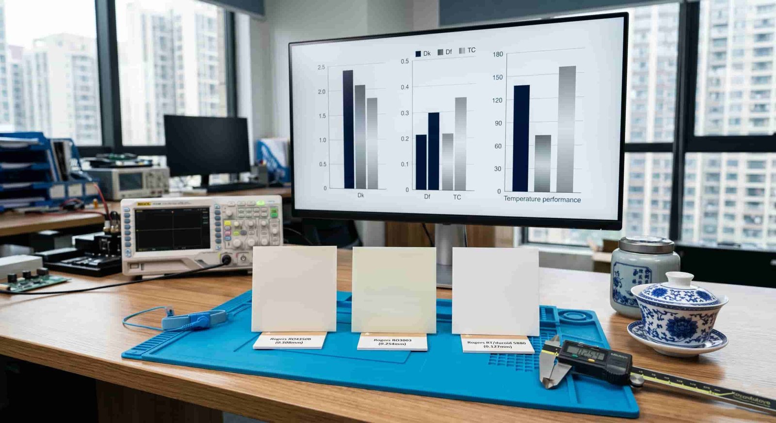
Conclusion
High frequency PCB for aerospace and defense applications requires a higher standard of material selection, process control, inspection, and documentation than commercial RF PCB. Rogers RO4350B, RO3003, and RT5880 are the most widely used materials for airborne radar, electronic warfare, satellite communication, and avionics applications. IPC Class 3 workmanship, wide temperature range reliability, full traceability, and compatibility with applicable military and aerospace standards are core requirements.
Early engagement with an experienced high frequency PCB manufacturer who understands aerospace and defense requirements reduces design iteration, supports qualification activities, and improves production consistency across prototype and production phases.