F4B is a family of Chinese-manufactured PTFE-based high frequency PCB laminates produced primarily by Wangling Electronics (旺灵电子, Taixing, China). The designation ‘F4B’ stands for Fluorine-4B — a reference to the PTFE (tetrafluoroethylene) base material. F4B materials cover Dk values from 2.20 to 6.15, spanning the same range as Rogers PTFE materials at significantly lower cost.
F4B is widely used in commercial RF and microwave PCB applications in China and increasingly in global commercial electronics where Rogers-certified documentation is not required. As a direct high frequency PCB factory, we hold F4BM220, F4BM255, F4BM265, F4BM300, F4B350, F4BTM400, F4BTM440, and F4BTM615 in regular production inventory and process them on the same PTFE plasma activation line as Rogers and Taconic PTFE materials.
Quick Summary
Key point: F4B materials are PTFE-based and require the same plasma or sodium activation hole wall treatment as Rogers RO3003 and RT5880 before copper plating. F4BM220 (Dk 2.20, Df 0.0010) is the closest F4B equivalent to Rogers RO3003 at Ka-band. F4BM300 (Dk 3.0, Df 0.0017) has higher Df than RO3003 (0.0010) — note this difference for loss-sensitive designs. F4B is appropriate for commercial RF applications below 15 GHz where Rogers brand certification is not specified. For aerospace, defense, or any program with Rogers specified on the fabrication drawing, Rogers materials are required.
F4B Material Grade Overview
The F4B family consists of two sub-series: the F4BM series (pure PTFE or PTFE composite, lower Dk) and the F4BTM series (PTFE ceramic composite, medium-to-high Dk). The complete range covers Dk from 2.20 to 6.15.
F4BM Series — Low to Medium Dk
F4BM220 — Ultra-Low Dk, Closest to Rogers RT5880
F4BM220 is the lowest-Dk grade in the F4B family. Its Dk of 2.20 and Df of 0.0010 make it the F4B material most comparable to Rogers RT5880 (Dk 2.2, Df 0.0009) and Taconic TLP-5 (Dk 2.2, Df 0.0009).
- Dk: 2.20 ±0.04, Df: 0.0010
- Rogers comparison: Rogers RT5880 (Df 0.0009) — F4BM220 Df is 11% higher, negligible for most commercial designs
- Standard thicknesses: 0.127 / 0.254 / 0.508 / 0.762 / 1.016 / 1.524 mm, custom thicknesses available
- Processing: PTFE — plasma activation required, same as Rogers RT5880
- Maximum lamination cycles: 2
- Best for: commercial EW and SIGINT simulation/test equipment, commercial broadband RF below 20 GHz, IoT and wireless devices where Rogers certification is not required
F4BM255 — Mid-Low Dk
F4BM255 (Dk 2.55, Df 0.0013) sits between F4BM220 and F4BM265 in the Dk range. There is no direct Rogers equivalent at Dk 2.55 — the closest is Taconic TLY-3 (Dk 2.33) and Rogers RT5870 (Dk 2.33), both lower, or F4BM265 at Dk 2.65.
- Dk: 2.55 ±0.05, Df: 0.0013
- Standard thicknesses: same as F4BM220
- Best for: commercial RF circuits requiring Dk between 2.33 and 2.65 for specific impedance or antenna geometry requirements
F4BM265 — Dk 2.65
F4BM265 (Dk 2.65, Df 0.0015) covers the Dk 2.65 range. Taconic TLA-6 (Dk 2.65, Df 0.0017) is a comparable material. F4BM265 has slightly lower Df than TLA-6.
- Dk: 2.65 ±0.05, Df: 0.0015
- Standard thicknesses: same range as F4BM220
- Best for: commercial RF modules requiring Dk ~2.65 for circuit geometry optimization
F4BM300 — Dk 3.0, Ka-Band Range
F4BM300 (Dk 3.0, Df 0.0017) is the F4B grade most often compared to Rogers RO3003 (Dk 3.0, Df 0.0010). The Dk is identical, but the Df is 70% higher than RO3003. This difference is meaningful for Ka-band and loss-sensitive designs.
- Dk: 3.0 ±0.05, Df: 0.0017
- Rogers comparison: Rogers RO3003 (Dk 3.0, Df 0.0010) — F4BM300 Df is 70% higher
- Standard thicknesses: same range as F4BM220
- Processing: PTFE — plasma activation required
- Best for: commercial Ka-band designs below 30 GHz where loss budget allows Df 0.0017, and Rogers RO3003 is not specified
Design guidance: For Ka-band (26.5–40 GHz) with a tight insertion loss budget, calculate the additional loss from F4BM300 Df 0.0017 vs RO3003 Df 0.0010 on your longest RF path. At 30 GHz over 50mm, the difference is approximately 0.3–0.5 dB. If this is within budget, F4BM300 is adequate. If not, Rogers RO3003 is the correct specification.
F4B350 — Dk 3.5, Comparable to Rogers RO4350B Range
F4B350 (Dk 3.5, Df 0.0025) covers the Dk 3.5 range, comparable to Rogers RO4350B (Dk 3.48) in dielectric constant but with lower Df than RO4350B (0.0037). Note that F4B350 is a PTFE material requiring plasma activation, while Rogers RO4350B is hydrocarbon ceramic and does not require PTFE activation.
- Dk: 3.5 ±0.05, Df: 0.0025
- Rogers comparison: Rogers RO4350B (Dk 3.48, Df 0.0037) — F4B350 has lower Df but requires PTFE process
- Best for: commercial RF below 15 GHz where Rogers RO4350B is over-specified for the application
F4BTM Series — Medium to High Dk PTFE Ceramic
F4BTM400 — Dk 4.0
F4BTM400 (Dk 4.0, Df 0.0030) is a PTFE ceramic material in the medium-Dk range. It is used for compact RF circuit designs where a Dk around 4.0 reduces antenna element dimensions compared to lower-Dk materials.
- Dk: 4.00 ±0.08, Df: 0.0030
- Standard thicknesses: same range as F4BM series
- Processing: PTFE ceramic — plasma activation required
- Best for: compact patch antenna designs, filters at frequencies where lower-Dk materials produce inconveniently large element sizes
F4BTM440 — Dk 4.4
F4BTM440 (Dk 4.4, Df 0.0033) covers the Dk 4.4 range — between FR4 (Dk ~4.5) and F4BTM400 in dielectric constant, but with much lower Df than FR4.
- Dk: 4.40 ±0.10, Df: 0.0033
- Note: Dk is close to FR4 but Df is much lower — a useful option when circuit geometry is optimized for Dk ~4.4 and low loss is required
- Best for: designs transitioning from FR4 to PTFE where same trace widths can be retained with better RF performance
F4BTM615 — High Dk, Maximum Miniaturization
F4BTM615 (Dk 6.15, Df 0.0045) is the highest-Dk F4B grade. It is directly comparable to Rogers RO3006 (Dk 6.15, Df 0.0020) in dielectric constant, though with higher Df.
- Dk: 6.15 ±0.12, Df: 0.0045
- Rogers comparison: Rogers RO3006 (Dk 6.15, Df 0.0020) — F4BTM615 Df is approximately 2× higher
- Best for: commercial compact antenna designs, filter miniaturization where Rogers RO3006 is not required and the higher Df is acceptable
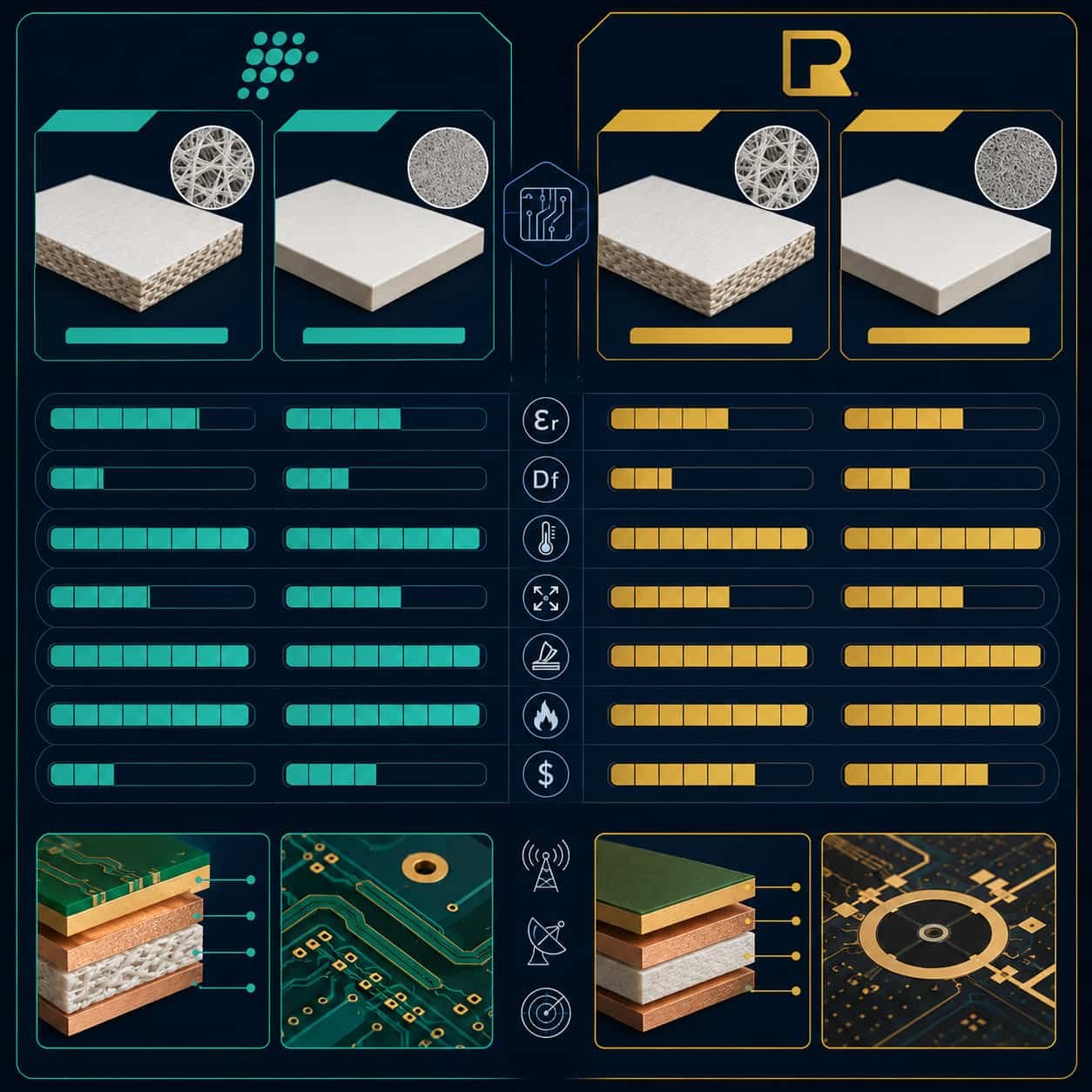
F4B vs Rogers: Honest Performance Comparison
F4B materials are genuine PTFE laminates with real RF performance. The comparison with Rogers is straightforward — F4B grades have matching or comparable Dk values to Rogers equivalents, but generally higher Df. The Df difference varies by grade and the application determines whether it matters.
Where F4B Df Difference Is Negligible
- F4BM220 vs Rogers RT5880: Df 0.0010 vs 0.0009 — 11% difference, negligible for commercial designs below 20 GHz with typical trace lengths
- F4BM255 vs Rogers RT5870: Df 0.0013 vs 0.0012 — 8% difference, negligible
- Short trace lengths below 50 mm at frequencies below 15 GHz: Df difference between F4B and Rogers produces less than 0.2 dB additional insertion loss — within most commercial link budgets
Where F4B Df Difference Matters
- F4BM300 vs Rogers RO3003: Df 0.0017 vs 0.0010 — 70% difference. At 30 GHz over 100 mm feed network, this adds approximately 0.5–1.0 dB additional loss. For tight Ka-band link budgets, this matters.
- F4BTM615 vs Rogers RO3006: Df 0.0045 vs 0.0020 — 125% difference. For compact antenna designs where coupling efficiency depends on low dielectric loss, Rogers RO3006 maintains better antenna efficiency.
- Any application above 30 GHz: at higher frequencies, the Df difference between F4B and Rogers produces proportionally more insertion loss per unit length. Rogers materials are preferred above 30 GHz.
- EW and SIGINT receivers: for commercial EW simulation or test equipment where every dB of insertion loss affects dynamic range, Rogers RT5880 (Df 0.0009) is preferred over F4BM220 (Df 0.0010) even for commercial programs
Where F4B Cannot Substitute for Rogers
- Aerospace and defense programs: Rogers-certified material documentation with lot traceability is required — F4B does not provide this
- Programs with Rogers specified on the fabrication drawing: substitution requires written customer approval
- IPC Class 3 military programs: Rogers certification is part of the qualification record — F4B is not qualified
- Above 30 GHz with tight insertion loss budgets: Rogers RO3003 Df advantage becomes significant at Ka-band extremes
Factory perspective: We use F4BM220 and F4BM300 regularly for commercial customers who need PTFE performance at lower material cost than Rogers. For these customers — commercial IoT devices, industrial sensors, commercial VSAT terminals — F4B is a technically sound choice. The question we always ask in engineering review is: does the insertion loss difference between F4B and Rogers affect this specific design’s performance specification? If the answer is no, F4B is a valid cost optimization.
F4B PCB Manufacturing Process
F4B materials are PTFE-based and require the same specialized manufacturing processes as Rogers RO3003 and RT5880. A factory that can produce Rogers PTFE materials reliably can produce F4B materials with the same process.
Hole Wall Activation
PTFE does not bond to copper without prior surface activation. This applies to all F4B grades without exception.
- Plasma activation: our factory uses plasma etch as the standard activation method for all F4B PTFE materials
- Sodium naphthalene: alternative wet chemical method — also effective for F4B
- Without activation: electroless copper will not bond reliably — boards pass initial test and fail in thermal cycling
- This is the single most important manufacturing requirement for F4B PCB — a factory that skips activation produces unreliable boards
Drilling
- PTFE-specific spindle speed: lower than FR4 — prevents heat buildup and hole wall smearing
- Lower feed rate: reduces mechanical deformation of soft PTFE
- PTFE-specific entry and exit materials: prevents surface burring
- Same parameters as Rogers RO3003 and RT5880 — no difference between F4B and Rogers PTFE for drilling
Lamination
- PTFE-specific press temperature and pressure profile
- Maximum 2 press cycles — same limit as Rogers PTFE
- Bonding film: PTFE-compatible bonding film required for multilayer F4B stackups
- For F4B + FR4 hybrid: PTFE-compatible bonding film at the interface — not standard FR4 prepreg
Controlled Impedance
- Impedance calculation using confirmed production Dk from material certificate — not nominal values
- F4B Dk tolerances: typically ±0.04 to ±0.12 depending on grade — wider than Rogers
- TDR verification: impedance coupon on every production panel
- Standard tolerance: ±10% for traces ≥50Ω, ±5Ω for traces <50Ω
For controlled impedance specification, see Why Controlled Impedance Matters in RF PCB Manufacturing. For PTFE manufacturing challenges, see PTFE PCB Manufacturing Challenges and Process Considerations.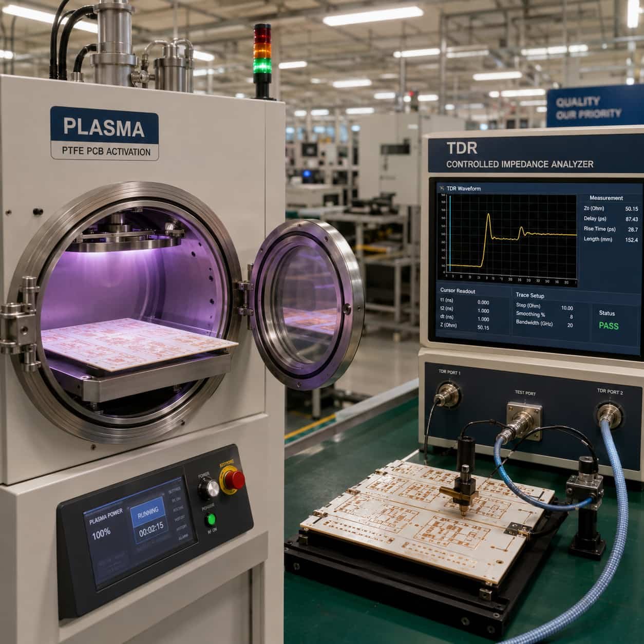
Applications Where F4B PCB Is the Right Choice
Commercial IoT and Industrial RF Modules
IoT devices, industrial wireless sensors, and commercial RF modules operating below 10 GHz are the primary application area for F4B PCB. At these frequencies with typical trace lengths, the Df difference between F4B and Rogers produces negligible insertion loss, and Rogers-certified documentation is not required.
- Industrial IoT sensors (2.4 GHz, 5.8 GHz): F4BM220 or F4BM255 — adequate performance, cost-effective
- Short-range radar modules (24 GHz): F4BM220 — commercially viable at this frequency
- RFID and NFC reader PCB (860 MHz, 13.56 MHz): FR4 is adequate at these frequencies — F4B unnecessary
- Commercial building automation RF (915 MHz): FR4 adequate — F4B not needed
Commercial VSAT and Satellite Terminal
Commercial VSAT ground terminals for C-band and Ku-band where Rogers-certified documentation is not required can use F4B materials at lower cost than Rogers.
- C-band VSAT (3.7–4.2 GHz): F4BM220 — adequate Dk and Df for C-band commercial terminal
- Ku-band VSAT (10.7–12.75 GHz uplink): F4BM220 — commercial terminal where Rogers not required
- Ka-band commercial terminal (17–20 GHz downlink): F4BM220 or F4BM300 — verify insertion loss budget
5G Commercial CPE and Small Cells
Commercial 5G customer premises equipment (CPE) and small cells at sub-6 GHz frequencies where Rogers RO4350B is the standard but cost optimization is important.
- 5G CPE at 3.5 GHz: F4BM300 or F4BM265 — commercial CPE, Rogers not specified
- 5G indoor small cell: F4BM220 or F4BM300 — depends on frequency and loss budget
- 5G mmWave module (28 GHz): Rogers RO3003 preferred — F4BM300 Df 0.0017 may be tight at 28 GHz
Cost Optimization for Commercial Rogers PCB Designs
Commercial designs originally specified with Rogers materials can sometimes be optimized to F4B after engineering review confirms the F4B Df is within the insertion loss budget.
- Original spec: Rogers RT5880 → Potential alternative: F4BM220 — Df only 11% higher, commercial applications only
- Original spec: Rogers RO3003 → Potential alternative: F4BM300 — Df 70% higher, verify budget at operating frequency
- Requires: engineering review with actual trace lengths and operating frequency before substitution
- Not applicable: any program with Rogers specified on the fabrication drawing — requires written customer approval
F4B PCB Manufacturing at Riching PCB
We produce F4B PCB from the same PTFE manufacturing process line as Rogers and Taconic PTFE materials. F4B is not a secondary or occasional process for us — it is regular production.
F4B Grades in Production Inventory
- F4BM220: 0.127 / 0.254 / 0.508 / 0.762 / 1.016 / 1.524 mm — standard inventory
- F4BM255: same standard thickness range
- F4BM265: same standard thickness range
- F4BM300: same standard thickness range
- F4B350: 0.254 / 0.508 / 0.762 / 1.016 / 1.524 mm
- F4BTM400: same range as F4BM series
- F4BTM440: same range
- F4BTM615: same range
Manufacturing Specifications
- Hole wall activation: plasma activation — standard for all F4B grades
- Minimum drill diameter: 0.1 mm advanced, 0.2 mm standard
- Maximum aspect ratio: 14:1 advanced, 10:1 standard
- Layer count: 2–32 standard, up to 50 advanced
- Controlled impedance: ±10% standard, ±8% advanced — TDR verified every lot
- Maximum lamination cycles: 2 — same as all PTFE materials
- IPC Class: Class 2 standard for commercial F4B PCB; Class 3 available on request
- Surface finish: ENIG standard; immersion silver for higher frequency applications
What to Prepare for F4B PCB Quotation
- F4B grade — specify F4BM220, F4BM300, F4BTM400, etc. or provide operating frequency for recommendation
- Substrate thickness — confirm standard availability before stackup finalization
- Complete stackup with layer sequence and copper weight
- Operating frequency or frequency range
- Controlled impedance requirements — target value and tolerance
- Application type — commercial IoT, VSAT, 5G CPE, etc.
- Whether Rogers-certified documentation is required (if yes, specify Rogers grade)
- IPC Class requirement
- Surface finish
- Quantity
For a complete file checklist, see What Files Are Needed for a High Frequency PCB Quotation?. For ZY material comparison, see ZY High Frequency PCB Material. For Rogers material selection, see Rogers PCB Material Selection Guide.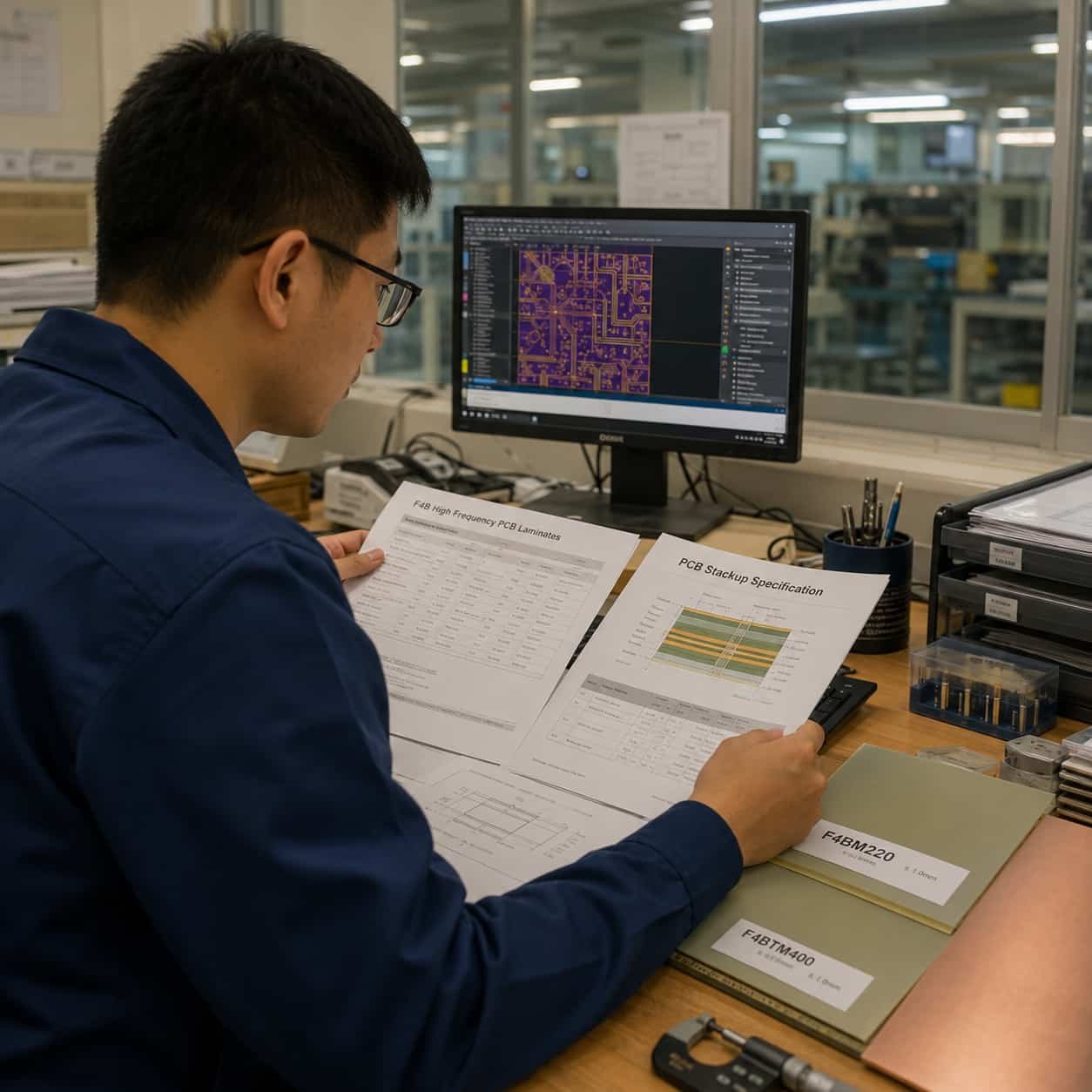
Conclusion
F4B PCB materials are genuine PTFE laminates with real RF performance, available at lower cost than Rogers and Taconic for commercial applications where Rogers-certified documentation is not required. F4BM220 covers most commercial RF designs below 20 GHz with performance close to Rogers RT5880. F4BM300 covers commercial Ka-band applications where the higher Df compared to Rogers RO3003 is within the design’s insertion loss budget. F4BTM series covers compact antenna and filter designs requiring higher Dk.
The same PTFE manufacturing requirements apply to F4B as to Rogers — plasma activation, PTFE-specific drill parameters, maximum 2 lamination cycles. As a direct high frequency PCB factory with all F4B grades in regular production inventory and a PTFE plasma activation process line, we review F4B material specifications with the same engineering rigor as Rogers projects — confirming insertion loss feasibility, Dk tolerance impact on impedance, and process compatibility before every order.