The majority of ‘high frequency PCB manufacturers’ appearing in search results are trading companies — businesses that receive your order, add a margin, and outsource production to a factory. For standard FR4, this is often acceptable. For Rogers RO3003, RT5880, Taconic TLY-5, and other PTFE materials, it is a significant risk: the trading company’s factory may not have genuine PTFE plasma activation capability, may use the wrong bonding film for hybrid stackups, or may not verify controlled impedance on every production lot.
Riching PCB is the factory. When you send files to us, our engineering team — the same team that operates the production equipment — reviews your stackup, calculates impedance using production Dk values, confirms bonding film availability, and verifies that your design is within our confirmed process limits before production begins. No intermediary. No markup. No outsourcing of your high frequency PCB to a third party.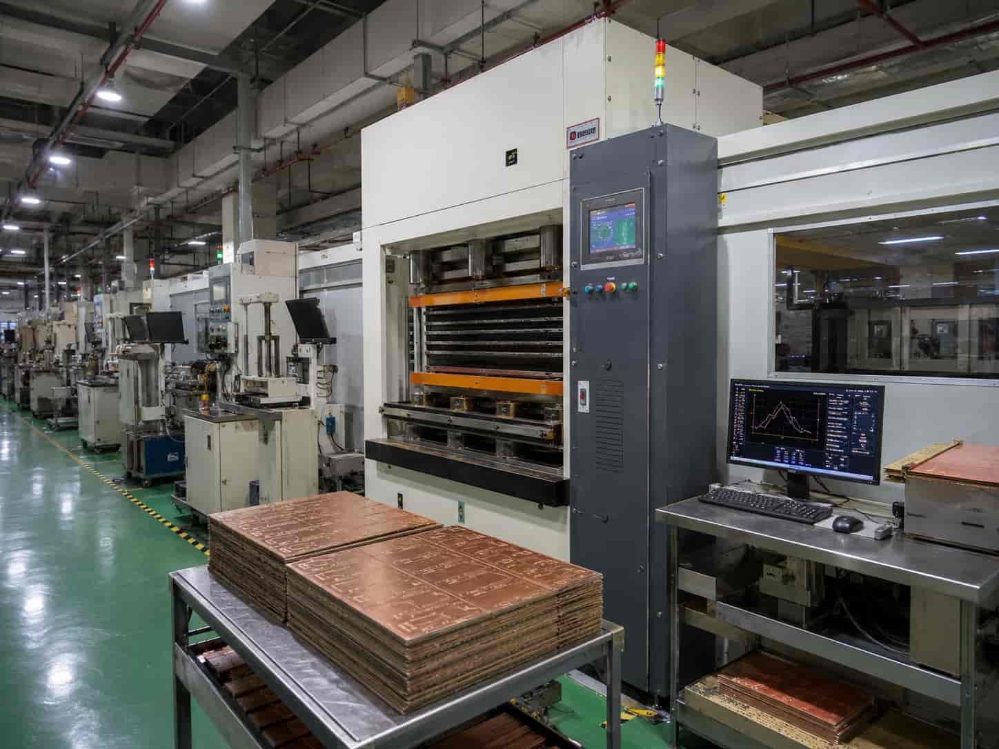
Manufacturing Capability at a Glance
High Frequency PCB Materials We Stock
We hold the following materials in regular production inventory in our Shenzhen factory. These are not materials we order on demand — they are in our warehouse, confirmed available for production.
Rogers Materials
- Rogers RO4350B: 0.101 / 0.168 / 0.254 / 0.338 / 0.422 / 0.508 / 0.762 / 1.524 mm — most widely used RF PCB material globally, FR4-compatible process
- Rogers RO4003C: 0.203 / 0.305 / 0.406 / 0.508 / 0.813 / 1.524 mm — lower Df than RO4350B for X-band and Ku-band
- Rogers RO3003: 0.127 / 0.254 / 0.508 / 0.762 / 1.524 mm — PTFE ceramic, Ka-band, 77 GHz automotive, defense AESA
- Rogers RO3003G2: 0.254 mm — tighter Dk ±0.03 for high-volume 77 GHz production
- Rogers RT5880: 0.127 / 0.254 / 0.381 / 0.508 / 0.787 / 1.575 / 3.175 mm — PTFE glass, EW 2–18 GHz, W-band
- Rogers RT5870: same thickness range as RT5880
- Rogers RO3006: 0.127 / 0.254 / 0.635 / 1.270 mm — high Dk PTFE, compact antenna
- Rogers RO3010: 0.127 / 0.254 / 0.635 / 1.270 mm — very high Dk PTFE, maximum miniaturization
- Rogers RO6010: 0.127 / 0.254 / 0.635 / 1.27 / 1.905 / 2.54 mm — ceramic PTFE, high Dk
- Rogers bonding films: RO4450F (for RO4350B/RO4003C hybrids) and Rogers 2929 bondply (for PTFE hybrids) — both in stock
Taconic (AGC) Materials
- Taconic TLY-5A / TLP-5 / TLY-5: Dk 2.17–2.22, Df 0.0009 — equivalent to Rogers RT5880
- Taconic TLY-3: Dk 2.33, Df 0.0012 — equivalent to Rogers RT5870
- Taconic RF-35: Dk 3.5, Df 0.0018 — lower Df than Rogers RO4350B
- Taconic RF-60A: Dk 6.5, Df 0.0038 — high Dk compact antenna
- Taconic CER-10: Dk 10.0, Df 0.0035 — very high Dk, maximum miniaturization
F4B (Wangling) Materials
- F4BM220: Dk 2.20, Df 0.0010 — cost-effective PTFE for commercial RF
- F4BM255, F4BM265, F4BM300: mid-range Dk PTFE
- F4B350: Dk 3.5, Df 0.0025
- F4BTM400, F4BTM440, F4BTM615: medium to high Dk PTFE ceramic
ZY (中英) and Other Materials
- ZYF220D, ZYF225DA, ZYF265D, ZYF300CA-P, ZYF350CA — Chinese-manufactured PTFE alternatives
- Isola 370HR, Astra MT77 — available by order
- Arlon high frequency materials — available by order
- Standard FR4 (high-Tg) — for hybrid stackups and digital layers
For material selection guidance, see High Frequency PCB Materials for RF Applications. For Rogers grade comparison, see Rogers PCB Material Selection Guide.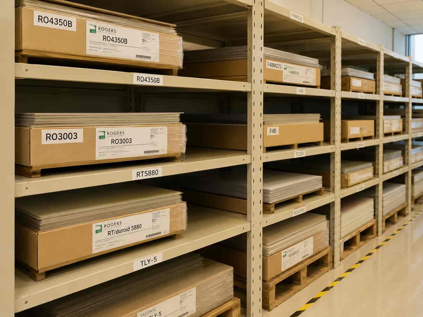
Process Capability
Drilling
- Minimum mechanical drill diameter: 0.1 mm (advanced), 0.2 mm (standard)
- Maximum aspect ratio: 15:1 (extreme limit), 14:1 (advanced), 10:1 (standard)
- Hole position tolerance: ±0.05 mm (advanced), ±0.075 mm (standard)
- Hole diameter tolerance PTH: ±0.05 mm (advanced), ±0.076 mm (standard)
- PTFE-specific drill parameters: confirmed for Rogers RO3003, RT5880, Taconic TLY-5, F4B series
PTFE Hole Wall Activation
- Method: plasma activation — our standard process for all PTFE materials
- Materials covered: Rogers RO3003, RO3003G2, RO3006, RO3010, RT5880, RT5870; Taconic TLY-5A, TLP-5, TLY-5, TLY-3, RF-35, RF-60A, CER-10; F4B series; ZY series
- Without this step PTFE PTH reliability fails under thermal cycling — we never skip it
Lamination
- Maximum press cycles: 3 for Rogers hydrocarbon (RO4350B, RO4003C); 2 for all PTFE materials
- Bonding films in stock: Rogers RO4450F for hydrocarbon hybrids; Rogers 2929 bondply for PTFE hybrids
- Layer count: 2–32 standard, up to 50 layers advanced
- Minimum dielectric thickness: 0.064 mm CORE with copper foil (standard), 0.05 mm (advanced)
Imaging and Etching
- Minimum outer layer line width: 2.5 mil (advanced), 3 mil (standard)
- Minimum inner layer line width: 2.7 mil (advanced), 3 mil (standard)
- Line width tolerance: ±1 mil for traces below 10 mil
Controlled Impedance
- Standard tolerance: ±10% for traces ≥50Ω; ±5Ω for traces below 50Ω
- Advanced tolerance: ±8%
- Verification: TDR measurement on impedance coupon — every production lot
- Calculation: using confirmed production Dk from Rogers/Taconic material certificate lot — not nominal values
Copper Plating
- PTH copper plating: 20–50 µm range
- IPC Class 3: 25 µm average, 20 µm minimum at any point — verified by microsection
- Void limit: ≤5% per hole for IPC Class 3, ≤10% for Class 2
Surface Finish
- ENIG: nickel 120–300 µin, gold 1–5 µin — standard for most high frequency PCB
- ENEPIG: nickel 120–300 µin, palladium 1–2 µin, gold 1–5 µin — aerospace and wire bond
- Immersion Silver: 0.15–0.40 µm — preferred above 10 GHz
- Immersion Tin: 1.0–1.3 µm
- OSP: 0.20–0.60 µm
- Gold finger: hard gold available
Board Specifications
- Maximum panel size: 480×800 mm standard, 610×914 mm advanced
- Finished board thickness: 0.1–10.0 mm
- Board thickness tolerance: ±0.1 mm for thickness below 1.0 mm; ±10% for 1.0 mm and above
- Warpage: ≤0.75% for SMT boards, ≤1.5% for through-hole boards
- Impedance test coupon: placed on panel edge, TDR measurement records retained
Direct Factory vs Trading Company: What the Difference Means for Your Order
Most buyers sourcing high frequency PCB from China encounter both direct factories and trading companies. Understanding the difference helps avoid quality problems — particularly for PTFE materials where process capability verification is critical.
What a Trading Company Does
- Receives your files and specifications
- Adds a margin — typically 15–40%
- Sends your files to a factory — often the lowest-cost factory that accepts the order
- Has no direct visibility into whether the factory has plasma activation capability
- Cannot answer specific technical questions about the manufacturing process
- Returns finished boards to you — quality depends entirely on the factory they used
What a Direct Factory Like Riching PCB Does
- Receives your files and our own engineers review them — the same engineers who run the production equipment
- DFM review flags issues before production: wrong bonding film, impedance out of range, via aspect ratio exceeding capability
- Impedance calculation uses confirmed production Dk from the Rogers material certificate lot — not generic values
- Plasma activation performed in-house on our own equipment — confirmed before every PTFE order
- TDR impedance measurement performed in-house on every production lot
- Microsection analysis performed in our own metallographic lab
- Rogers-certified material certificates with lot numbers available for aerospace and defense programs
- Direct communication — technical questions answered by the engineer, not a sales representative
How to verify: Ask any potential high frequency PCB supplier: ‘What hole wall activation method do you use for Rogers RT5880?’ A direct factory with PTFE capability answers immediately — plasma or sodium naphthalene. A trading company or FR4-only factory gives a vague answer. This single question separates genuine PTFE capability from claimed capability.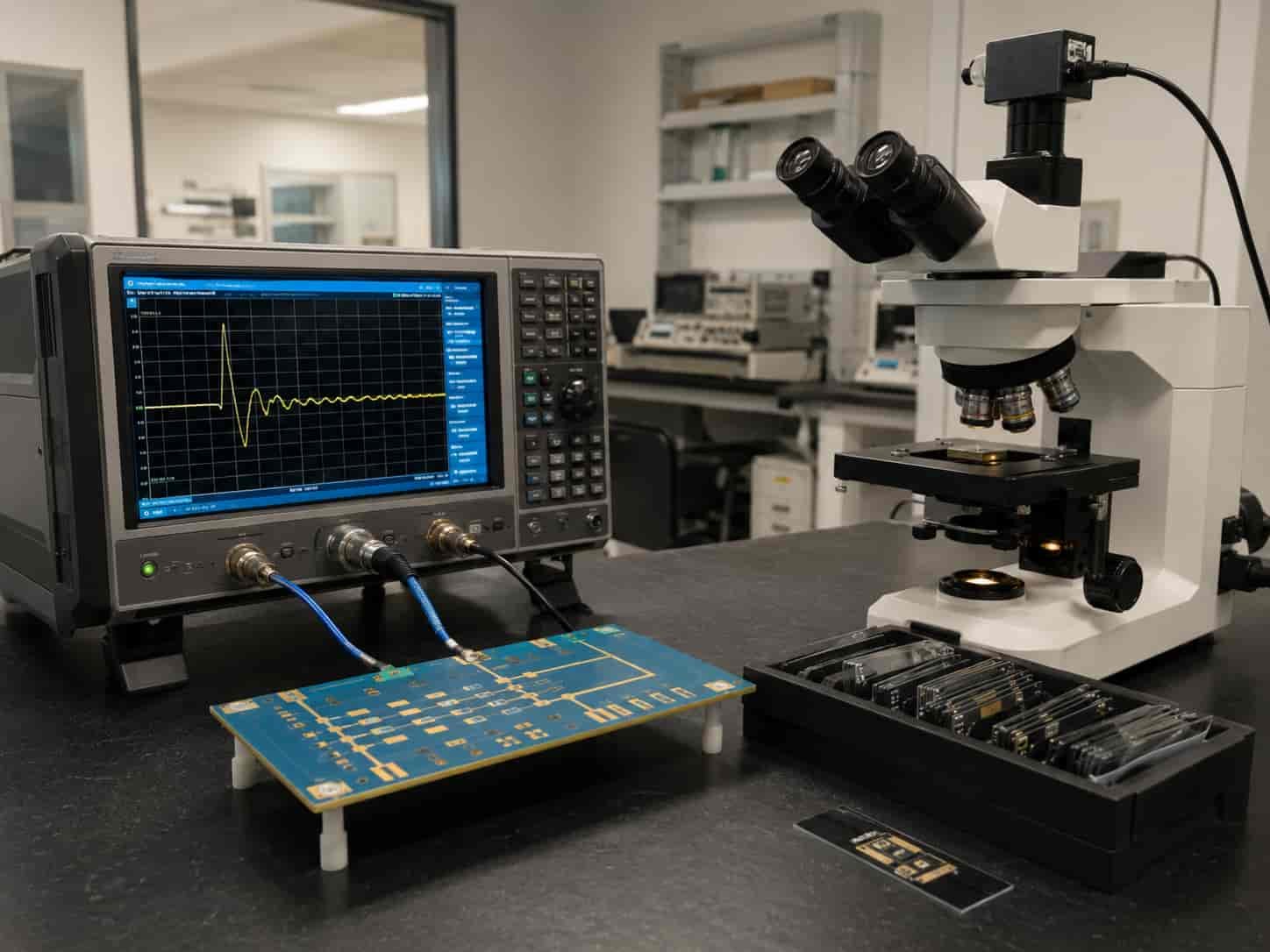
Applications We Regularly Produce
Aerospace and Defense
- Electronic warfare receiver PCB: Rogers RT5880, 2–18 GHz, IPC Class 3
- Ka-band missile seeker PCB: Rogers RO3003, 0.254 mm, ENIG or immersion silver
- Airborne AESA radar feed network: Rogers RO3003 + FR4 hybrid, multilayer
- SIGINT and ELINT receiver PCB: Rogers RT5880, ultra-low loss
- Avionics communication PCB: Rogers RO4350B, IPC Class 3
See: High Frequency PCB for Aerospace and Defense
Radar Systems
- 77 GHz automotive radar: Rogers RO3003 or RO3003G2, 0.254 mm
- S-band surveillance radar: Rogers RO4350B, large panel
- X-band fire control radar: Rogers RO4003C or RO3003
- Ground-based air defense radar: Rogers RO3003, multilayer
See: High Frequency PCB for Radar Systems
Satellite Communication
- Ka-band SATCOM terminal: Rogers RO3003, 0.127–0.254 mm
- Ku-band VSAT: Rogers RO4003C or RO3003
- C-band ground terminal: Rogers RO4350B
See: High Frequency PCB for Satellite Communication
5G and Commercial Wireless
- 5G massive MIMO base station antenna (3.5 GHz): Rogers RO4350B, up to 480×800 mm panel
- 5G mmWave module (28/39 GHz): Rogers RO3003, 0.254 mm, plasma activation
- WiFi and IoT RF modules: Rogers RO4350B or F4B
See: High Frequency PCB for 5G Communication Devices
Quality Standards and Equipment
In-House Testing Equipment
- AOI (Automated Optical Inspection): every inner layer and outer layer
- TDR impedance tester: controlled impedance measurement on every production lot
- Flying probe electrical tester: 100% electrical test for IPC Class 3
- Metallographic microscope: via cross-section microsection analysis
- 2D measurement system: dimensional verification
- Copper thickness tester: PTH copper plating verification
Quality Standards
- IPC Class 2: commercial and industrial applications
- IPC Class 3: aerospace, defense, and high-reliability applications
- ISO 9001: quality management system certification
- IPC-6012: qualification and performance specification for rigid printed boards
- Rogers-certified material documentation: available for all Rogers production lots
How to Place an Order
As a direct factory, we accept orders directly from engineers and buyers worldwide. There is no minimum order quantity requirement for prototype orders.
What to Send
- Gerber files — all copper layers, solder mask, board outline
- NC drill file
- Stackup drawing — material grade, layer thickness, copper weight per layer
- Controlled impedance requirements if applicable
- Surface finish, IPC Class, quantity, delivery requirement
Contact
- WhatsApp: +86 13760473650 — fastest response for technical questions and urgent quotations
- Website: richingpcb.com
- Quotation turnaround: 24–48 business hours for standard designs after DFM review
- Prototype lead time: 5–7 working days for most 2–4 layer Rogers designs
- Production lead time: 10–15 working days depending on complexity and quantity
For the complete file checklist, see What Files Are Needed for a High Frequency PCB Quotation?. For factory evaluation guidance, see How to Evaluate a High Frequency PCB Manufacturer.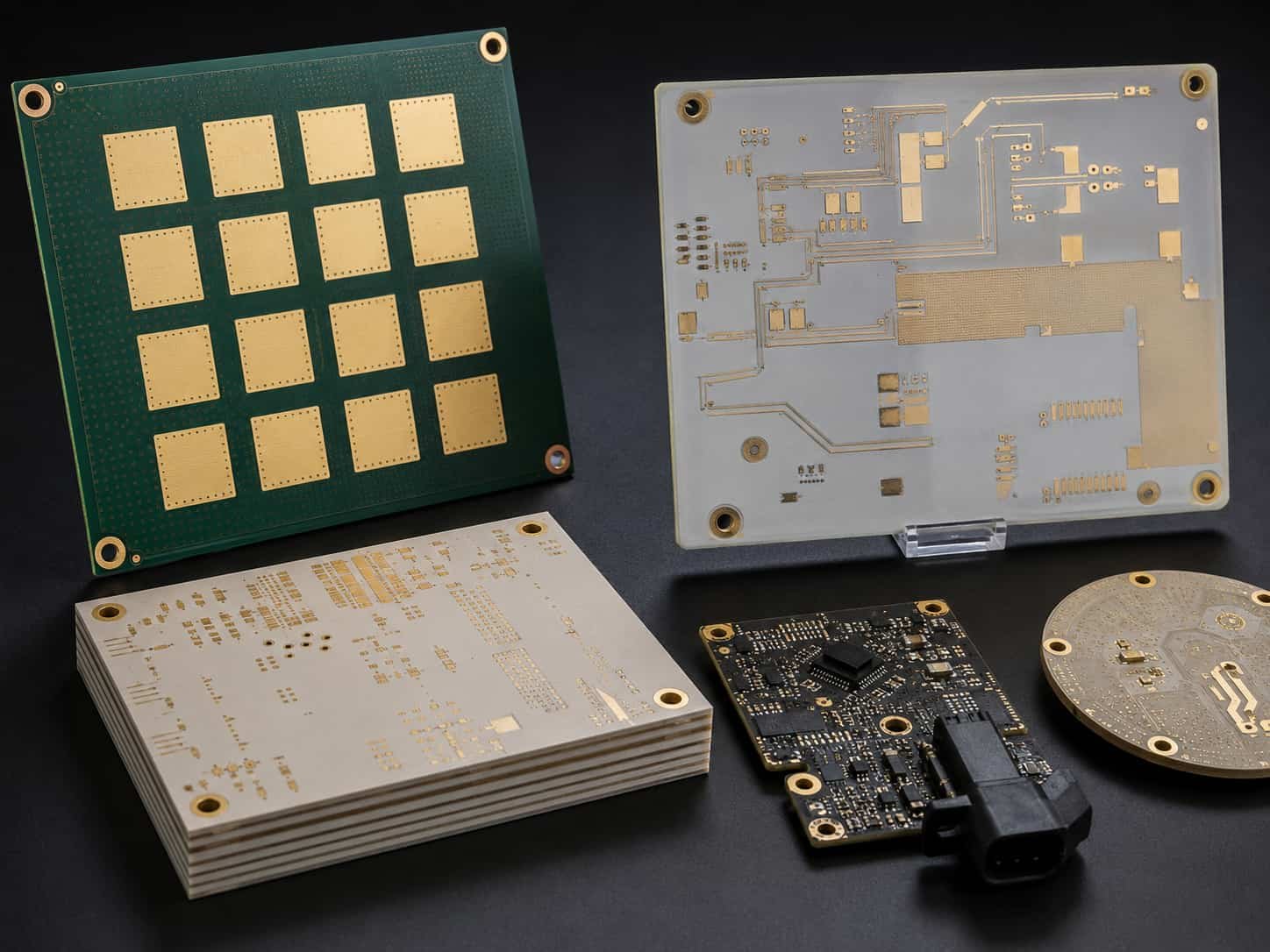
Conclusion
Riching PCB is a direct high frequency PCB manufacturer in Shenzhen, China, with Rogers, PTFE, Taconic, F4B, and ZY materials in production inventory and our own plasma activation equipment, TDR impedance testing, and metallographic lab on site. We produce everything from simple 2-layer Rogers RO4350B prototype boards to complex 32-layer hybrid PTFE multilayer stackups for aerospace and defense applications.
The difference between ordering from a direct factory and a trading company is not just price — it is process visibility, DFM quality, and PTFE capability verification. If you are specifying high frequency PCB with Rogers RO3003, RT5880, or any PTFE material, the factory’s ability to answer ‘plasma activation’ when you ask about PTFE hole wall treatment is the single most reliable indicator that your boards will be built correctly. We can answer that question — and all the other technical questions that matter for your design.