
Rogers RO3003 PCB: Ka-Band, 77 GHz and Defense Applications Guide
Rogers RO3003 is the standard PTFE ceramic substrate for Ka-band (26.5–40 GHz), 77 GHz automotive radar, and high-via-density defense RF applications including AESA arrays and missile seekers. Its combination of tight Dk tolerance, low z-axis CTE, and Df 0.0010 makes it the preferred choice wherever high via density and dimensional consistency matter as much as low loss. This guide covers material properties, trace width by thickness, via density and thermal cycling considerations, comparison with Rogers RT5880, and manufacturing requirements. Riching PCB stocks RO3003 in 0.127mm and 0.254mm with in-house plasma activation — no material wait, 7–10 working day prototype.
Home » High Frequency PCB » Rogers RO3003 PCB: Ka-Band, 77 GHz and Defense Applications Guide
Table of Contents
Rogers RO3003 Material Properties
| Property | Rogers RO3003 | Rogers RT5880 | Rogers RO4350B |
|---|---|---|---|
| Dk (10 GHz) | 3.00 ±0.04 | 2.20 ±0.02 | 3.48 ±0.05 |
| Df (10 GHz) | 0.0010 | 0.0009 — lowest | 0.0037 |
| Dk variation 2–18GHz | <2% | <2% — best | Moderate variation |
| Dk temp. coeff. (ppm/°C) | +13 | −125 | +50 |
| z-axis CTE (ppm/°C) | 24 — low, reliable | 237 — high, via risk | 32–46 |
| x-y CTE (ppm/°C) | 17 | 31 | 14 / 16 |
| Thermal conductivity (W/m·K) | 0.50 | 0.20 | 0.69 |
| Processing | PTFE — plasma activation | PTFE — plasma activation | FR4-compatible |
| Bonding film | Rogers 2929 bondply | Rogers 2929 bondply | Rogers RO4450F |
| Max lamination cycles | 2 | 2 | 3 |
| Via density suitability | High density OK | Low–medium only | Medium–high OK |
| Primary applications | Missile seeker, AESA, 77GHz automotive, Ka-band SATCOM | EW 2–18GHz, SIGINT, W-band 75–110GHz | 5G, radar, VSAT, RF below 12GHz |
RO3003’s defining characteristic relative to other PTFE materials is its low z-axis CTE — 24 ppm/°C, roughly 10× lower than RT5880’s 237 ppm/°C. In multilayer designs with high via density (AESA feed networks, dense via fences for isolation), each via barrel experiences stress during thermal cycling proportional to the surrounding material’s CTE mismatch with copper. RO3003’s low z-axis CTE is why it is the standard choice for designs where via count is high and thermal cycling reliability is critical — even though RT5880 has marginally lower Df.
Insertion Loss and Frequency Performance
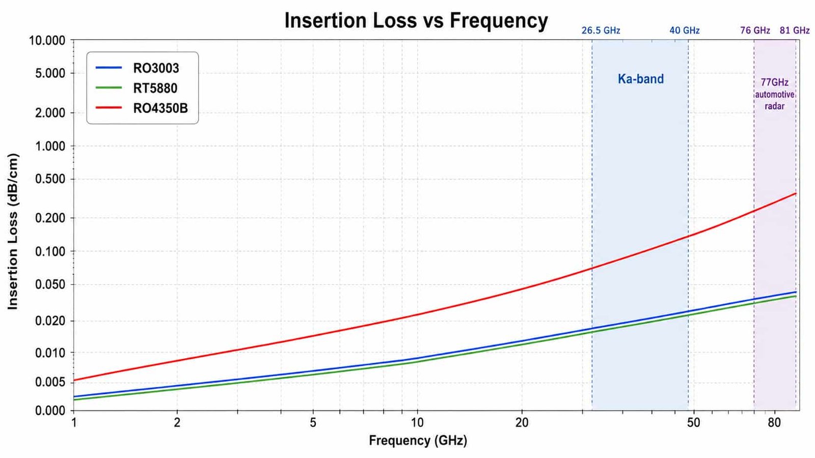
RO3003’s Df of 0.0010 at 10GHz remains low enough to be the standard choice through Ka-band (26.5–40GHz) and 77GHz automotive radar applications. At these frequencies, RO3003’s combination of low loss, tight Dk tolerance (±0.04, tightened further in RO3003G2 to ±0.03), and low via-related thermal stress makes it the default material for radar and satellite communication front-ends operating above 20GHz.
50Ω Trace Width by Thickness
| Substrate Thickness | Copper Weight | 50Ω Trace Width | Typical Application |
|---|---|---|---|
| 0.127mm | 0.5oz | ~0.28mm | 77GHz automotive radar, W-band |
| 0.254mm | 0.5oz | ~0.55mm | Ka-band, 28GHz 5G mmWave |
| 0.254mm | 1oz | ~0.64mm | Ka-band standard build |
| 0.508mm | 1oz | ~1.24mm | X-band, general microwave |
| 0.762mm | 1oz | ~1.86mm | Lower frequency, power handling |
The 0.127mm substrate with 0.5oz copper producing approximately 0.28mm trace width is the standard build for 77GHz automotive radar patch antenna arrays — this trace width fits within the λ/2 element spacing (~1.95mm at 77GHz) required to avoid grating lobes. See our full breakdown in the 77GHz radar PCB design guide for element spacing and via fence design rules specific to this application.
Rogers RO3003 vs RT5880 — Choosing Between the Two PTFE Materials
| Requirement | Choose RO3003 | Choose RT5880 |
|---|---|---|
| Primary frequency | Ka-band (26.5–40GHz) | 2–18GHz wideband, W-band (75–110GHz) |
| Via density | High density (AESA, dense feed networks) | Low–medium only |
| 77GHz automotive radar (production) | ✅ RO3003G2 tighter Dk tolerance ±0.03 | Not preferred — CTE via risk in production |
| Thermal conductivity priority | ✅ 0.50 W/m·K | 0.20 W/m·K — lower |
| Widest instantaneous bandwidth (2–18GHz) | Adequate | ✅ Dk stability across full band |
| Absolute minimum Df | 0.0010 | ✅ 0.0009 — marginally lower |
RO3003 and RT5880 have comparable Df at 10GHz but are optimized for different design priorities. For a detailed breakdown of RT5880’s advantages in wideband EW and W-band applications, see Rogers RT5880 PCB guide. The short version: choose RO3003 when via density is high or the application is Ka-band/77GHz production radar; choose RT5880 when the requirement is wideband coverage (2–18GHz) or W-band (75–110GHz) where RO3003’s higher loss becomes limiting.
77GHz Automotive Radar — Why RO3003 Is Preferred Over RT5880 in Production
For 77GHz automotive radar specifically, RO3003 (particularly RO3003G2 with tightened Dk tolerance ±0.03) is preferred over RT5880 for two production-specific reasons: tighter lot-to-lot Dk consistency supports antenna element phase repeatability across production volume, and RO3003’s low z-axis CTE (24 ppm/°C) provides better via fatigue resistance across the automotive thermal cycling range (-40°C to +85°C) — a requirement RT5880’s much higher z-axis CTE (237 ppm/°C) does not meet as reliably at scale.
Manufacturing Requirements
RO3003 is a PTFE ceramic material requiring the same core process steps as other PTFE laminates: in-house plasma hole wall activation before copper plating, PTFE-specific drill parameters (lower spindle speed than FR4), Rogers 2929 bondply for hybrid stackups (not RO4450F, which is for RO4350B/RO4003C), and a maximum of 2 lamination press cycles.
- Hole wall activation: plasma, in-house — outsourced or delayed activation compromises long-term via reliability
- Bonding film: Rogers 2929 bondply for RO3003-to-FR4 hybrid stackups
- Maximum lamination cycles: 2 — applies to the full stackup if hybrid construction is used
- Minimum drill: 0.1mm advanced (laser), 0.2mm standard — via fence spacing at 77GHz requires laser-drilled microvias
- Impedance control: ±10% standard, ±5% TDR-verified available
What to Specify for RO3003 PCB Quotation
- Substrate thickness — confirm from 0.127mm, 0.254mm, 0.508mm, 0.762mm, 1.524mm standard range
- Copper weight per layer — 0.5oz for 77GHz/W-band, 1oz for general Ka-band
- Complete stackup with material, thickness, copper weight per layer
- Bonding film requirement if hybrid — Rogers 2929
- Controlled impedance target, tolerance, and layer
- Via density and thermal cycling requirement — helps assess whether RO3003 or RT5880 is the better fit
- IPC Class — 2 standard, 3 for defense/aerospace programs
Rogers RO3003 PCB — Q&A
Common questions about RO3003 applications, comparison with RT5880, and why it's preferred for 77GHz automotive radar production.
What is Rogers RO3003 used for?
RO3003 (Dk 3.0, Df 0.0010) is the standard PTFE material for Ka-band (26.5-40GHz), 77GHz automotive radar, and high-via-density defense applications including AESA arrays and missile seekers. Its low z-axis CTE (24 ppm/°C) suits designs with high via density where thermal cycling reliability is critical.
What is the difference between Rogers RO3003 and RT5880?
Both have comparable Df at 10GHz. Key difference: RO3003's z-axis CTE (24 ppm/°C) is ~10x lower than RT5880 (237 ppm/°C), better for high via density. RT5880's lower Dk (2.20) and Dk stability across 2-18GHz make it standard for wideband EW and W-band, while RO3003 is preferred for Ka-band and 77GHz production.
Why is RO3003 preferred over RT5880 for 77GHz automotive radar?
RO3003G2's tightened Dk tolerance (±0.03) provides better lot-to-lot phase consistency, and its low z-axis CTE provides better via fatigue resistance across automotive thermal cycling (-40°C to +85°C). RT5880 remains preferred for W-band defense where insertion loss matters more than via reliability.
What is the 50Ω trace width for Rogers RO3003 at 0.127mm?
Approximately 0.28mm with 0.5oz copper — the standard build for 77GHz automotive radar patch antenna arrays, fitting within the λ/2 element spacing (~1.95mm) required to avoid grating lobes.
Rogers RO3003 In Stock — 0.127mm & 0.254mm, In-House Plasma Activation
No material procurement wait. TDR impedance verification every lot. Rogers 2929 bondply in stock for hybrid stackups. IATF16949 certified. 7–10 day prototype, no MOQ.
Rogers RO3003 PCB Manufacturer → WhatsAppRequest a PCB Quote
Upload your Gerber ZIP file and project requirements. Our engineering team will review your PCB material, stackup, impedance needs, surface finish, and production quantity before quoting.
Please prepare:
- Gerber files in ZIP format
- PCB material or stackup requirements
- Controlled impedance notes if available
- Prototype or batch production quantity