Rogers RT5880 is the lowest-loss standard PCB material available. Df of 0.0009 at 10 GHz — lower than Rogers RO3003 (0.0010), significantly lower than Rogers RO4350B (0.0037), and approximately 22 times lower than standard FR4 (~0.020). Two properties make RT5880 the material of choice for specific applications: its Df is the lowest of any standard Rogers material, and its Dk varies less than 2% from 1 GHz to 110 GHz — providing consistent insertion loss and impedance across the widest frequency range of any standard laminate.
These two properties make Rogers RT5880 the standard material for electronic warfare receivers covering 2–18 GHz, SIGINT collection systems, and W-band (75–110 GHz) applications. As a direct Rogers PCB factory with RT5880 in production inventory across all standard thicknesses and plasma activation in-house, we build RT5880 PCB for EW, SIGINT, and W-band programs in regular production.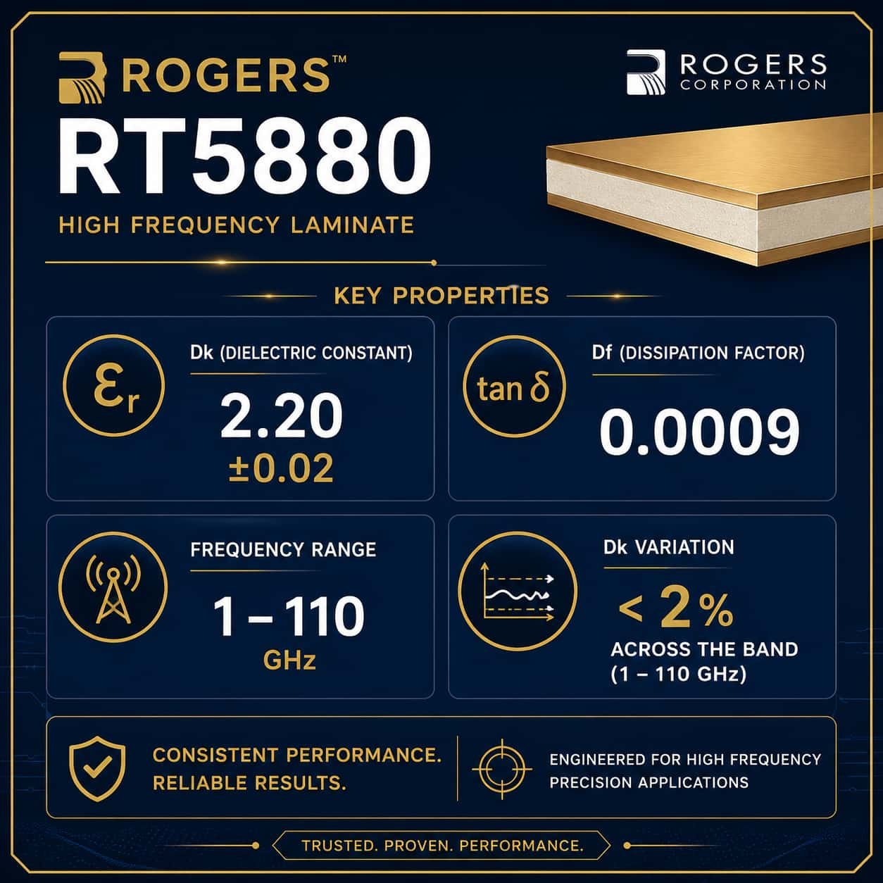
Quick Summary
Key point: Rogers RT5880 (Dk 2.20 ±0.02, Df 0.0009, PTFE glass) is specified for two application types: wideband EW systems covering 2–18 GHz where consistent low Df across the full band is the priority, and W-band (75–110 GHz) applications where it is the only viable standard PCB material. RT5880 is a PTFE material requiring plasma hole wall activation. Its z-axis CTE of 237 ppm/°C is significantly higher than Rogers RO3003 (24 ppm/°C) — for high via density designs at Ka-band and above, RO3003 provides better via fatigue reliability. RT5880 is the correct choice for low via density wideband designs where the Df advantage and frequency-stable Dk are the priority.
Rogers RT5880 Material Properties
Dielectric Constant (Dk)
- Nominal Dk: 2.20 at 10 GHz — lowest Dk of any standard Rogers material
- Dk tolerance: ±0.02 — tighter than RO4350B (±0.05) and RO3003 (±0.04)
- Dk frequency stability: less than 2% variation from 1 GHz to 110 GHz — exceptional wideband consistency
- Dk temperature coefficient: −125 ppm/°C — Dk decreases slightly with temperature
- Practical significance: consistent Dk from 2–18 GHz means consistent impedance across the full EW band — no frequency-dependent impedance shift that would affect wideband receiver performance
Dissipation Factor (Df)
- Df at 10 GHz: 0.0009 — lowest of any standard Rogers PCB material
- Df at 35 GHz: approximately 0.0011
- Df at 77 GHz: approximately 0.0014
- Comparison: Rogers RO3003 Df 0.0010 at 10 GHz — RT5880 is marginally lower but comparable
- Comparison: Rogers RO4350B Df 0.0037 at 10 GHz — RT5880 is 4× lower
- At W-band (77–110 GHz): RT5880 is the only standard material with acceptable insertion loss — no other commercial laminate provides comparable Df at these frequencies
Dk Frequency Stability: The Key RT5880 Advantage for EW
The defining advantage of RT5880 for wideband EW is not just low Df — it is the combination of low Df and stable Dk across the full 2–18 GHz EW band. Rogers RO3003 has comparable Df at 10 GHz, but its Dk of 3.0 produces narrower traces than RT5880 (Dk 2.2) — and at the low end of the EW band (2 GHz), wider traces reduce copper loss relative to the higher Dk material.
- RT5880 Dk variation 2–18 GHz: less than 2% — consistent impedance across the full EW band
- RT5880 Dk variation 2–110 GHz: less than 2% — consistent from EW through W-band
- RO4350B Dk variation 1–18 GHz: larger — produces frequency-dependent impedance shift in wideband designs
Thermal and Mechanical Properties
- z-axis CTE: 237 ppm/°C — significantly higher than Rogers RO3003 (24 ppm/°C)
- x-y CTE: 31 ppm/°C — higher than RO3003 (17 ppm/°C) and FR4 (14–17 ppm/°C)
- Tg: greater than 500°C — PTFE, no practical glass transition temperature
- Thermal conductivity: 0.20 W/m·K — lower than RO3003 (0.50 W/m·K)
- Moisture absorption: 0.02% — lowest of any standard Rogers material, excellent Dk stability in humid environments
z-axis CTE warning: RT5880’s z-axis CTE of 237 ppm/°C is 10× higher than Rogers RO3003 (24 ppm/°C). In a multilayer PCB with high via density, each via barrel undergoes significant stress during thermal cycling. For EW designs with moderate via count, RT5880 is reliable. For designs requiring high via density — such as a AESA array with hundreds of RF via fences — RO3003’s lower z-axis CTE provides better via fatigue resistance. Always evaluate via count and thermal cycling requirements before specifying RT5880 for a multilayer design.
Rogers RT5880 Standard Thicknesses
- 127 mm: W-band (77–110 GHz) and very compact EW circuits
- 254 mm: standard for W-band and upper EW band (above 18 GHz)
- 381 mm: EW circuits requiring slightly wider traces
- 508 mm: most common for 2–18 GHz EW receiver PCB — provides good trace width for wideband circuits
- 787 mm: lower frequency EW or specific mechanical requirements
- 575 mm: mechanical substrate or low-frequency applications
- 175 mm: thick substrate for specific power handling requirements
Impedance Calculation for Rogers RT5880
Rogers RT5880 has a lower Dk than RO3003 (2.2 vs 3.0), which means the 50Ω trace on RT5880 is wider than on RO3003 for the same substrate thickness. This is an advantage for EW circuits — wider traces have lower conductor loss at microwave frequencies.
50Ω Microstrip Trace Width on Rogers RT5880
- RT5880 0.127 mm substrate, 0.5 oz copper: 50Ω trace ≈ 0.33 mm (13 mil)
- RT5880 0.254 mm substrate, 0.5 oz copper: 50Ω trace ≈ 0.69 mm (27 mil)
- RT5880 0.254 mm substrate, 1 oz copper: 50Ω trace ≈ 0.55 mm (22 mil)
- RT5880 0.508 mm substrate, 1 oz copper: 50Ω trace ≈ 1.16 mm (46 mil)
- RT5880 0.787 mm substrate, 1 oz copper: 50Ω trace ≈ 1.84 mm (72 mil)
EW design note: For wideband EW receiver PCB on RT5880 0.508mm, the 50Ω trace width of approximately 1.16mm is wide enough to keep conductor loss low at both 2 GHz and 18 GHz. This is one of the reasons RT5880 is preferred over RO3003 for wideband EW — the lower Dk produces wider traces with less conductor loss at the lower end of the EW band.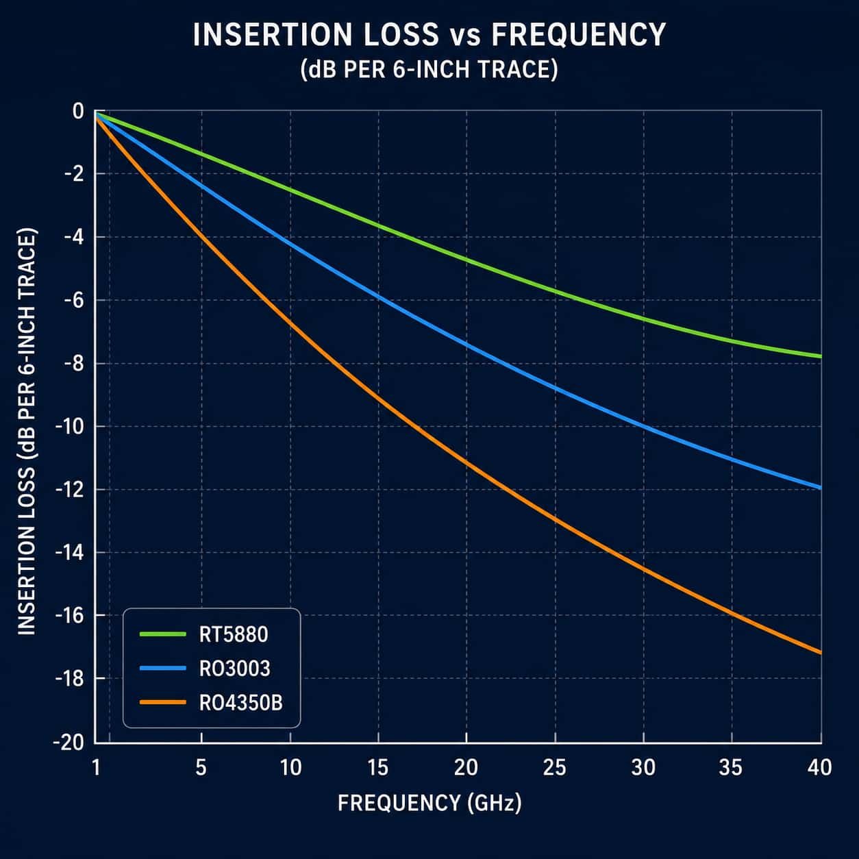
Rogers RT5880 Manufacturing Process
Rogers RT5880 is a PTFE glass material. Its manufacturing requirements are identical to Rogers RO3003 in all critical areas — plasma activation, PTFE-specific drilling, Rogers 2929 bondply, and 2-cycle lamination limit. A factory that can produce RO3003 reliably can produce RT5880 with the same process.
Hole Wall Activation — Same as RO3003
- Method: plasma activation — our standard PTFE process for RT5880
- Without activation: copper bonds weakly to RT5880 PTFE hole walls, fails under thermal cycling
- Same process as RO3003, Taconic TLY-5, and all other PTFE materials
Drilling
- PTFE-specific spindle speed and feed rate — same considerations as RO3003
- RT5880 is mechanically softer than RO3003 at elevated temperatures — slightly more care needed at thin substrates (0.127mm)
- Minimum drill: 0.1mm advanced, 0.2mm standard
Bonding Film
- Rogers 2929 bondply — same as RO3003, same as Taconic PTFE
- NOT Rogers RO4450F — that is for RO4350B and RO4003C only
- NOT standard FR4 prepreg — creates impedance discontinuity at PTFE-FR4 interface
Lamination
- Maximum 2 press cycles — strictly observed
- PTFE-specific temperature and pressure profile
- For RT5880 + FR4 hybrid stackups: 2 cycles maximum, set by RT5880
- x-y CTE mismatch RT5880 (31 ppm/°C) vs FR4 (14–17 ppm/°C): warpage analysis recommended for large-panel hybrid designs
For full PTFE process details, see PTFE PCB: Material Properties, Manufacturing Process and Applications.
Rogers RT5880 Applications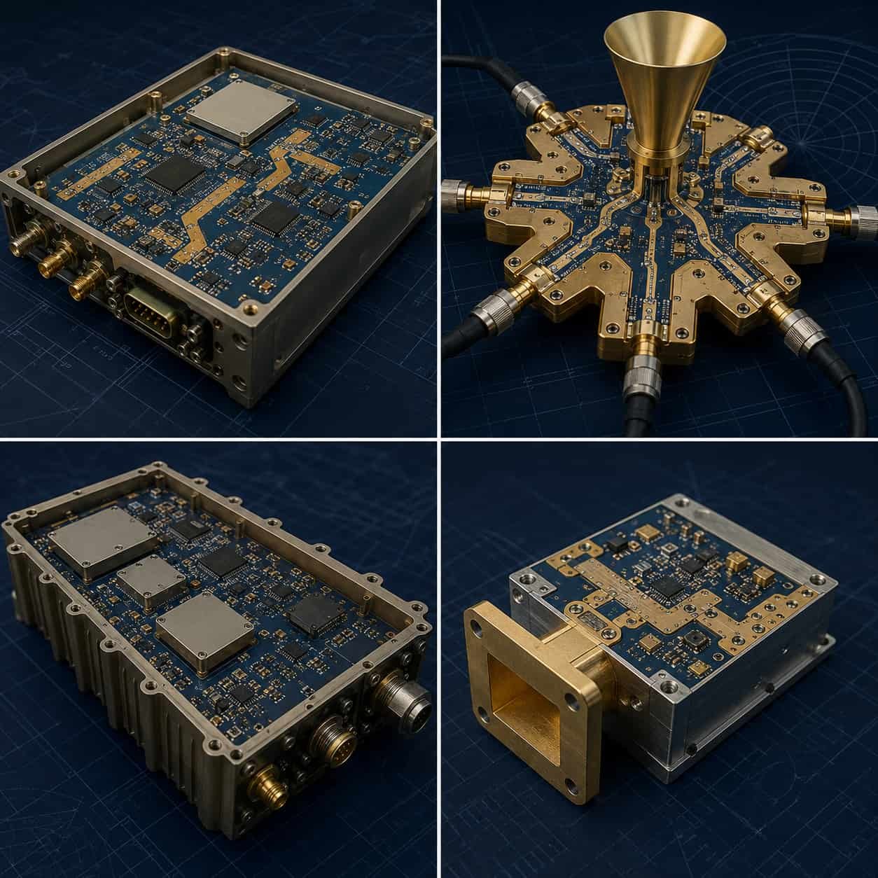
Electronic Warfare Receivers (2–18 GHz)
Airborne and shipborne electronic warfare systems — ESM (Electronic Support Measures), RWR (Radar Warning Receivers), and jammer front-end circuits — covering the 2–18 GHz range are the primary application for Rogers RT5880. The requirement is consistent low loss from 2 GHz through 18 GHz in a single design, which no other standard material provides as well as RT5880.
- Typical frequency coverage: 2–18 GHz instantaneous bandwidth
- Key requirement: consistent Dk and Df across the full band — RT5880 Dk variation less than 2% from 2–18 GHz
- Typical substrate: RT5880 0.508mm with 1 oz copper
- Quality standard: IPC Class 3, Rogers-certified material documentation
- Surface finish: ENIG or ENEPIG for defense IPC Class 3
See: Rogers PCB for Electronic Warfare Systems
SIGINT and ELINT Collection Systems
SIGINT (Signals Intelligence) receivers and ELINT (Electronic Intelligence) collection systems require the widest possible instantaneous bandwidth with the lowest possible insertion loss from the antenna to the first active stage. RT5880 is specified for the RF collection PCB in these systems for the same reason as EW receivers — consistent low Df across the widest possible frequency range.
- Frequency range: 0.5–40 GHz for broadband SIGINT, some systems extend to W-band
- Material: RT5880 for systems covering 2–18 GHz or wider
- Hybrid approach: RT5880 for 2–18 GHz input stages + RO3003 for Ka-band stages in multi-band systems
W-Band Applications (75–110 GHz)
Rogers RT5880 is the only commercially available standard PCB laminate that provides acceptable insertion loss at W-band frequencies. At 77 GHz and above, all other standard materials — RO4350B, RO3003, FR4 — produce too much insertion loss for practical use. RT5880’s Dk of 2.2 also produces the widest possible trace geometry at W-band, which minimizes conductor loss.
- 77 GHz sensing (non-automotive): RT5880 on 0.127mm or 0.254mm substrate
- E-band backhaul (71–86 GHz): RT5880 — standard material for high-data-rate point-to-point links
- W-band imaging: RT5880 0.127mm
- Antenna element at 77 GHz on RT5880 0.254mm: approximately 1.3mm × 1.3mm
- 50Ω trace at 77 GHz on RT5880 0.127mm: approximately 0.33mm (13 mil) — within standard manufacturing capability
W-band vs 77 GHz automotive: For 77 GHz automotive radar in high-volume production, Rogers RO3003 is more common than RT5880 because RO3003G2’s tighter Dk tolerance (±0.03) provides better lot-to-lot consistency, and RO3003’s lower z-axis CTE (24 vs 237 ppm/°C) provides better via reliability in the automotive thermal cycling range (-40°C to +85°C). RT5880 is preferred for W-band defense applications where insertion loss performance is prioritized over thermal cycling via reliability.
Tactical Communication and Link-16 / TTNT
Wideband tactical communication systems — including Link-16 (969–1206 MHz) and TTNT (Tactical Targeting Network Technology, 2–18 GHz) — specify RT5880 for the RF subsystem PCB when wideband frequency coverage and low insertion loss are both required.
Rogers RT5880 vs RO3003: Choosing Between the Two PTFE Materials
RT5880 and RO3003 are both PTFE materials with comparable Df at 10 GHz. The choice between them is driven by three factors:
Choose RT5880 When:
- Wideband frequency coverage is required: 2–18 GHz or wider. RT5880 Dk is stable across this range; RO3003 Dk is also stable but its higher Dk (3.0 vs 2.2) produces narrower traces with higher conductor loss at the low end of the EW band.
- W-band (75–110 GHz): RT5880 is the only viable standard material. RO3003 insertion loss at W-band is significantly higher.
- Low via density design: RT5880’s high z-axis CTE (237 ppm/°C) is only a concern when via count is high. For simple wideband EW boards with through-hole vias only, RT5880 is reliable.
- Minimum Df at any frequency: RT5880 Df 0.0009 is marginally lower than RO3003 Df 0.0010.
Choose RO3003 When:
- Ka-band (26.5–40 GHz) is the primary frequency: RO3003 is the standard Ka-band material.
- High via density required: RO3003 z-axis CTE 24 ppm/°C vs RT5880 237 ppm/°C — critical for via fatigue in multilayer AESA designs.
- 77 GHz automotive radar production: RO3003G2 Dk ±0.03 provides better lot-to-lot antenna consistency than RT5880.
- Better thermal conductivity needed: RO3003 0.50 W/m·K vs RT5880 0.20 W/m·K — matters for power handling.
For Rogers material selection guidance, see Rogers PCB Material Selection Guide. For RO3003 details, see Rogers RO3003 PCB: Ka-Band, 77 GHz and Defense Applications Guide.
Rogers RT5880 Production at Riching PCB
- RT5880 thicknesses in inventory: 0.127 / 0.254 / 0.381 / 0.508 / 0.787 / 1.575 / 3.175 mm
- Rogers 2929 bondply in stock for RT5880 hybrid stackups
- Hole wall activation: plasma — in-house, standard for all RT5880 orders
- Controlled impedance: ±10% standard, ±8% advanced — TDR verified every lot
- Minimum line width: 2.5 mil advanced (needed for W-band traces on 0.127mm)
- Minimum drill: 0.1 mm advanced, 0.2 mm standard
- Maximum lamination cycles: 2 — strictly observed
- IPC Class 3: available — for EW and defense programs
- Rogers-certified material certificates with lot numbers: available for all RT5880 production
- Large hybrid panel CTE analysis: available for RT5880 + FR4 hybrid designs requiring warpage review
What to Specify for Rogers RT5880 PCB Quotation
- Rogers RT5880 — confirm substrate thickness from standard range
- Copper weight per layer — 0.5 oz for W-band, 1 oz for EW
- Complete stackup — every layer with material, thickness, copper weight
- Bonding film — Rogers 2929 for hybrid stackups (factory confirms in stock)
- Controlled impedance — target, tolerance, layer, trace structure
- Operating frequency range — critical for confirming trace width feasibility at W-band
- Via density and thermal cycling requirement — helps assess z-axis CTE risk
- IPC Class — 2 or 3
- Rogers-certified documentation requirement
- Application type — EW, SIGINT, W-band sensing, tactical communication
- Quantity and delivery
For complete file checklist, see What Files Are Needed for a High Frequency PCB Quotation?.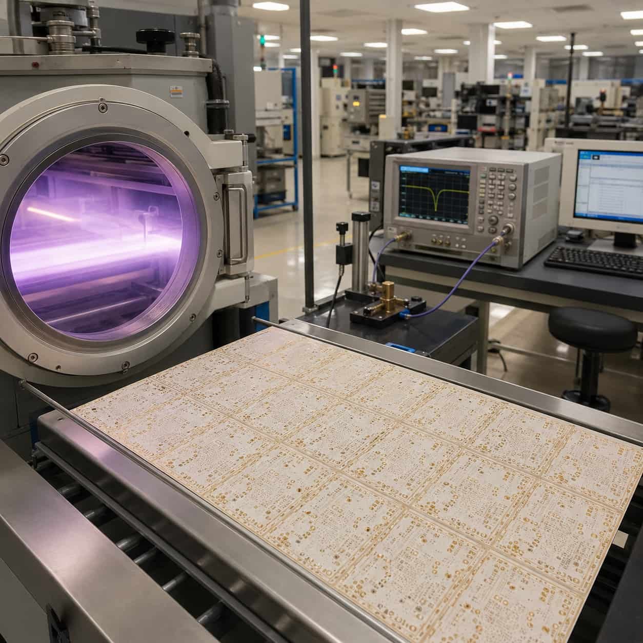
Conclusion
Rogers RT5880 is specified for two specific application types where no other standard material matches its performance: wideband EW systems covering 2–18 GHz where stable Dk and minimum Df across the full band are both required, and W-band (75–110 GHz) applications where it is the only viable standard commercial PCB laminate. Its Df of 0.0009 is the lowest of any Rogers material, and its Dk varies less than 2% from 1 GHz to 110 GHz.
The key manufacturing requirement — PTFE plasma activation, Rogers 2929 bondply, 2-cycle lamination limit — is identical to Rogers RO3003. As a direct Rogers PCB factory with RT5880 in regular production inventory and plasma activation in-house, we build RT5880 PCB for EW, SIGINT, and W-band programs. Every RT5880 order goes through engineering DFM review confirming PTFE process steps, impedance feasibility at operating frequency, and bonding film availability before production begins.