
Rogers FR4 Hybrid PCB Design Guide — Bonding Film Selection, Lamination Cycles and Cost Optimization
A Rogers FR4 hybrid PCB combines Rogers RF material on the layers that carry RF signal with standard FR4 on digital, power and ground layers — reducing material cost significantly while keeping full RF performance where it matters. Getting this right requires three things most designs get wrong on the first pass: using the correct bonding film at the material interface, respecting the lamination cycle limit set by whichever material in the stack is most restrictive, and placing layers so the RF signal path never needs to cross the hybrid interface unnecessarily. This guide covers all three.
Home » Rogers FR4 Hybrid PCB Design Guide — Bonding Film Selection, Lamination Cycles and Cost Optimization
Table of Contents
Why Hybrid Stackups Make Sense
| Stackup Approach | Relative Material Cost | RF Performance |
|---|---|---|
| All-Rogers (e.g. 8-layer, all RO4350B) | Highest — 100% Rogers cost on every layer | Full RF performance everywhere — often unnecessary |
| Hybrid — Rogers RF layers + FR4 digital/power | 30–50% lower typical | RF where needed, no compromise on RF layers |
| All-FR4 | Lowest material cost | No RF performance — not viable above ~1GHz |
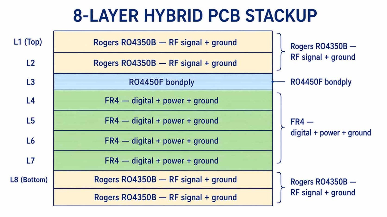
The core economic logic of a hybrid stackup: RF performance is only needed on the layers actually carrying RF signal. Digital baseband routing, power distribution, and ground reference layers do not benefit from Rogers material’s lower Df or tighter Dk tolerance — FR4 performs identically for these functions at a fraction of the cost. For a typical 8-layer board with 2 RF signal layers and 6 digital/power/ground layers, a hybrid stackup can reduce total material cost by 30–50% compared to an all-Rogers build, with zero compromise on RF performance.
Bonding Film Selection — The Most Common Mistake
| Interface | Correct Bonding Film | Why Standard FR4 Prepreg Fails |
|---|---|---|
| RO4350B / RO4003C to FR4 | Rogers RO4450F bondply | Dk mismatch and bonding reliability risk |
| RO3003 / RT5880 (PTFE) to FR4 | Rogers 2929 bondply | Does not bond reliably to PTFE — impedance discontinuity, delamination risk |
| Taconic PTFE to FR4 | Rogers 2929 bondply | Same PTFE bonding requirement |
| F4B PTFE to FR4 | Rogers 2929 bondply | Same PTFE requirement — confirm with fabricator |
| RO4350B to RO3003 (Rogers-to-Rogers) | Confirm with fabricator — material-specific | Different families may need compatibility check |
Using standard FR4 prepreg at a Rogers-to-FR4 interface — instead of the correct bonding film — is one of the most common and costly hybrid stackup mistakes. It is not a minor substitution: standard prepreg does not bond reliably to PTFE surfaces, and even at hydrocarbon ceramic interfaces it creates a Dk discontinuity that standard FR4 prepreg was never characterized for. This mistake often does not show up until reliability testing or field deployment — the board passes initial electrical test and delamination or performance issues appear later.
RO4450F — for hydrocarbon ceramic interfaces
RO4450F bondply is used specifically at the RO4350B or RO4003C to FR4 interface. Because these are hydrocarbon ceramic materials that process on FR4-compatible equipment, RO4450F is designed to bond reliably to both material types while maintaining consistent Dk at the transition.
Rogers 2929 — for PTFE interfaces
Rogers 2929 bondply is required at any PTFE material (RO3003, RT5880, Taconic PTFE grades, F4B PTFE grades) to FR4 interface. This is a different bondply from RO4450F — do not substitute one for the other. Standard FR4 prepreg is not an acceptable substitute at either interface type.
Lamination Cycle Constraints in Hybrid Stackups
| Hybrid Combination | Max Lamination Cycles | Constraint Source |
|---|---|---|
| RO4350B/RO4003C + FR4 | 3 cycles | Set by hydrocarbon ceramic material |
| RO3003/RT5880 (PTFE) + FR4 | 2 cycles | Set by PTFE material — the stricter limit governs |
| RO4350B + RO3003 + FR4 (three-material) | 2 cycles | Set by the PTFE component — always the limiting factor |
The maximum lamination cycle count for a hybrid stackup is always set by the most restrictive material in the stack — not averaged, not by the majority material. If your stackup includes any PTFE layer (RO3003, RT5880, Taconic, F4B) alongside hydrocarbon ceramic or FR4, the entire stackup is limited to 2 cycles, even though the hydrocarbon ceramic and FR4 portions alone could tolerate 3 or more. Plan your layer sequence and any blind/buried via requirements against this constraint before finalizing layout — see our
blind and buried via RF PCB design guide for how lamination cycle limits interact with blind via stage planning.
Layer Placement Rules
- Place RF signal layers as outer layers or immediately adjacent to the Rogers-FR4 interface — minimizing the number of layers the RF signal path must traverse on Rogers material
- Keep the ground reference plane directly beneath RF signal layers on the same Rogers material, not split across the hybrid interface
- Route digital high-speed signals on FR4 layers where FR4’s higher Dk and looser tolerance do not affect the design — reserve Rogers layers for RF only
- For designs with both RF and high-speed digital requirements, confirm whether FR4 alone meets digital signal integrity requirements before assuming Rogers is needed on those layers
Impedance at the Material Transition
Traces that must transition from a Rogers layer to an FR4 layer through a via experience an impedance step where the surrounding dielectric changes from Rogers Dk to FR4 Dk (and back, if the trace returns to a Rogers layer). For most digital and lower-frequency RF signals, this transition is negligible. For RF traces above 10GHz that must cross the hybrid boundary, minimize the transition length and consider whether the design can be restructured to keep the RF path entirely on Rogers material instead.
What to Specify on Your Hybrid Stackup Drawing
- Material and thickness for every layer explicitly — do not leave any layer as an assumed default
- Bonding film at each material interface — RO4450F or Rogers 2929, specified by interface, not assumed
- Maximum lamination cycle count for the full stackup — confirm this matches your via structure plan
- Impedance target and tolerance per layer — see controlled impedance PCB design guidefor full specification guidance
- Confirm bonding film stock availability with your fabricator before finalizing the design — not every factory stocks both RO4450F and Rogers 2929 as standard inventory
Rogers FR4 Hybrid PCB — Q&A
Common questions about hybrid stackup cost savings, bonding film selection, and lamination cycle constraints.
How much does a Rogers FR4 hybrid stackup save compared to all-Rogers?
Typically 30-50% lower material cost compared to an all-Rogers build, with no compromise on RF performance since only layers actually carrying RF signal need Rogers material.
What bonding film is used for Rogers RO4350B to FR4 hybrid stackups?
Rogers RO4450F bondply. Standard FR4 prepreg should not be used at this interface — it creates a Dk mismatch and bonding reliability risk that RO4450F is designed to avoid.
What bonding film is used for PTFE to FR4 hybrid stackups?
Rogers 2929 bondply, required for any PTFE material (RO3003, RT5880, Taconic, F4B) to FR4 interface. Different from RO4450F, which is only for hydrocarbon ceramic materials. Standard FR4 prepreg does not bond reliably to PTFE.
How many lamination cycles are allowed in a Rogers PTFE and FR4 hybrid stackup?
Maximum 2 cycles when any PTFE material is part of the stackup, even combined with materials that individually tolerate more. The most restrictive material always sets the limit for the entire stackup.
Hybrid Stackups — RO4450F and Rogers 2929 Both In Stock
Correct bonding film for every Rogers-FR4 interface, confirmed during DFM review. Rogers RO4350B, RO4003C, RO3003, RT5880 all in stock alongside FR4. 30–50% material cost savings vs all-Rogers builds.
Rogers PCB Manufacturer → WhatsAppRequest a PCB Quote
Upload your Gerber ZIP file and project requirements. Our engineering team will review your PCB material, stackup, impedance needs, surface finish, and production quantity before quoting.
Please prepare:
- Gerber files in ZIP format
- PCB material or stackup requirements
- Controlled impedance notes if available
- Prototype or batch production quantity