Rogers Corporation produces the most widely specified high frequency PCB laminates in the RF and microwave industry. Selecting the right Rogers material grade for your application determines insertion loss, impedance stability over temperature, via reliability under thermal cycling, and whether your design will meet its RF performance specification from prototype through production.
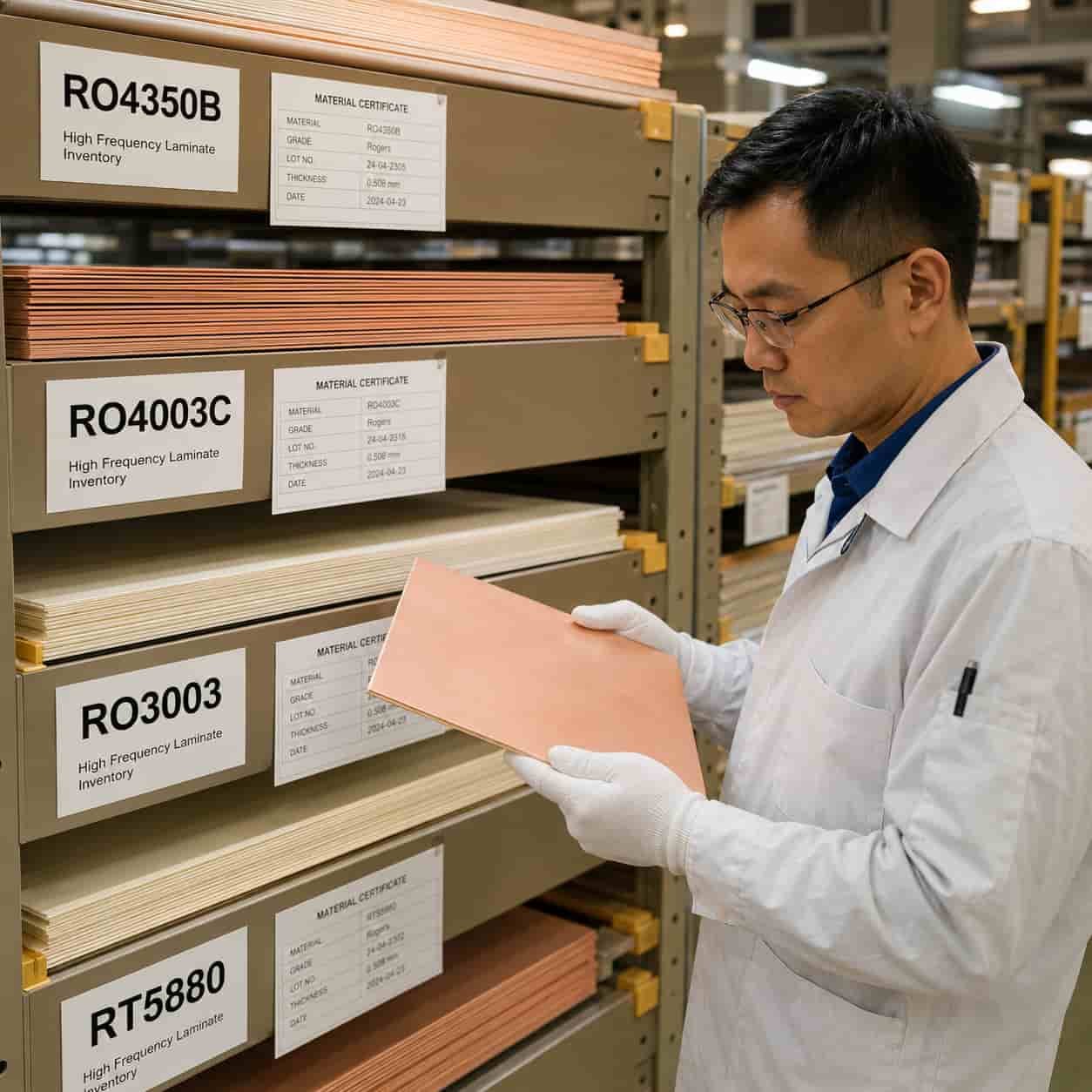
As a direct Rogers PCB manufacturer, we hold RO4350B, RO4003C, RO3003, RO3003G2, RT5880, RT5870, RO3006, RO3010, and RO6010 in production inventory. This guide covers the materials we build with every day — their properties, the differences that matter for real designs, and which grade to specify for which application.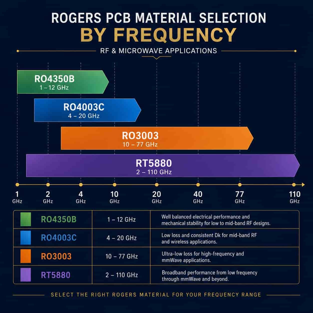
Quick Summary: Which Rogers Material for Which Application
Key point: Rogers RO4350B is the starting point for most RF and microwave PCB below X-band — it processes like FR4, it’s cost-effective, and its performance is proven across millions of defense and commercial boards. Rogers RO4003C provides 27% lower Df for applications where insertion loss budget is tight. Rogers RO3003 is the standard for Ka-band and any application requiring maximum Dk temperature stability. Rogers RT5880 is the only standard material for W-band and wide-band EW applications. When in doubt, start with RO4350B and upgrade only where the design requires it.
The Four Main Rogers Grades: What Distinguishes Each
Rogers RO4350B — The Universal Starting Point
Rogers RO4350B is the most widely used high frequency PCB material globally. It combines adequate RF performance from L-band through X-band with processing characteristics that are compatible with standard FR4 manufacturing equipment. This compatibility is the reason RO4350B became dominant: factories that build FR4 can adapt to RO4350B without PTFE-specific equipment or processes.
- Dk: 3.48 ±0.05 at 10 GHz — stable, well-characterized
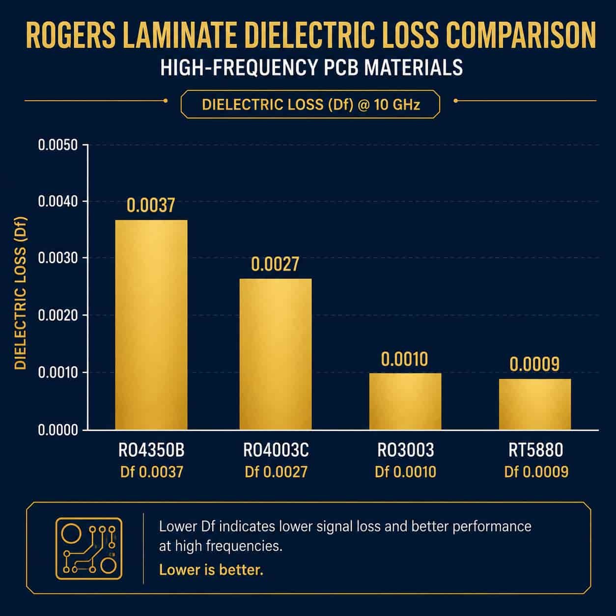
- Df: 0.0037 at 10 GHz — adequate for most designs below 12 GHz
- Tg: >280°C — far above any aerospace or defense operating temperature
- CTE x-y: 14/16 ppm/°C — close to copper (17 ppm/°C), good dimensional stability
- Processing: compatible with standard FR4 lamination equipment — requires Rogers RO4450F bondply for hybrid stackups
- Available thicknesses: 0.101mm to 1.524mm in standard grades
- Best for: L-band to X-band RF and microwave PCB, 5G sub-6 GHz, VSAT, WiFi modules, S-band and X-band radar, avionics below X-band
Rogers RO4003C — Lower Loss for Demanding X-Band and Above
Rogers RO4003C shares RO4350B’s processing characteristics — it uses the same FR4-compatible lamination process and the same RO4450F bondply — but achieves 27% lower Df. This reduction matters when insertion loss budget is tight or when operating frequency reaches the upper part of X-band and into Ku-band.
- Dk: 3.38 ±0.05 at 10 GHz
- Df: 0.0027 at 10 GHz — 27% lower than RO4350B
- Tg: >280°C — same thermal stability as RO4350B
- Processing: identical to RO4350B — same equipment, same bonding film
- Cost: approximately 20–35% higher than RO4350B for the same thickness
- Best for: X-band fire control radar with long antenna feed networks, Ku-band VSAT and military data links, applications where RO4350B loss is acceptable at one end of the board but becomes limiting at the antenna feed
When to upgrade from RO4350B to RO4003C: Calculate the insertion loss for your longest RF path at your highest operating frequency. If it exceeds your system noise figure budget, upgrade to RO4003C. If the loss is within budget, RO4350B is sufficient.
Rogers RO3003 — PTFE Base, Maximum Dk Stability
Rogers RO3003 is a PTFE-based ceramic-filled material. The PTFE base changes both the electrical properties and the manufacturing process requirements compared to the RO4000 hydrocarbon series. RO3003 requires PTFE-specific hole wall activation before copper plating and different lamination press profiles — but in return it delivers Df of 0.0010, a Dk temperature coefficient of +13 ppm/°C, and a z-axis CTE of 24 ppm/°C that makes it the most reliable choice for via fatigue in thermal cycling.
- Dk: 3.0 ±0.04 at 10 GHz — tightest Dk tolerance of the common Rogers grades
- Df: 0.0010 at 10 GHz — 73% lower than RO4350B
- Dk temperature coefficient: +13 ppm/°C — 4× more stable than RO4350B over -55°C to +125°C
- z-axis CTE: 24 ppm/°C — lowest of common Rogers materials, best via fatigue life
- Tg: >500°C (PTFE base — no practical glass transition)
- Processing: requires plasma or sodium activation for PTFE hole wall, PTFE-specific lamination parameters, maximum 2 press cycles
- Available thicknesses: 0.127mm to 1.524mm — 0.127mm enables Ka-band antenna design
- Best for: Ka-band radar and VSAT, 77GHz automotive radar, missile seeker PCB, defense AESA T/R modules, any application requiring stable Dk across wide temperature range
Rogers RT5880 — Ultra-Low Loss, Broadband
Rogers RT/duroid 5880 is a woven glass PTFE composite that achieves the lowest Df of any standard Rogers material — 0.0009 at 10 GHz — and maintains this low loss consistently across a remarkably wide frequency range. RT5880 is specified where minimum insertion loss across a broad instantaneous bandwidth is the primary requirement: electronic warfare receivers, W-band applications, satellite communication front-ends.
- Dk: 2.20 ±0.02 at 10 GHz — lowest Dk of standard Rogers materials, very stable
- Df: 0.0009 at 10 GHz — minimum of any standard PCB material
- Dk frequency stability: less than 2% variation from 1 GHz to 40 GHz — critical for wideband EW
- Tg: >500°C (PTFE base)
- z-axis CTE: 237 ppm/°C — significantly higher than RO3003, limits via reliability in severe thermal cycling
- Processing: same PTFE activation requirement as RO3003, maximum 2 press cycles
- Available thicknesses: 0.127mm to 3.175mm
- Best for: EW receivers (2–18 GHz), ESM and SIGINT, W-band (75–110 GHz), satellite communication Ku/Ka-band front-ends, any design requiring minimum loss across a wide frequency range
RT5880 via reliability caution: RT5880 z-axis CTE of 237 ppm/°C is 10× higher than RO3003 (24 ppm/°C). For designs with >500 thermal cycles in the qualification requirement, copper-filled vias are strongly recommended and via fatigue life must be analyzed. For missile guidance seekers and single-use applications, this constraint is less significant.
Additional Rogers Grades: When the Standard Grades Are Not Enough
Rogers RO3003G2 — Improved RO3003 for High-Volume Automotive
Rogers RO3003G2 is an evolution of RO3003 with tighter Dk tolerance (±0.03 vs ±0.04) and more consistent lot-to-lot electrical properties. It was developed for the high-volume automotive radar market where production consistency across millions of units is essential.
- Dk: 3.0 ±0.03 — tighter than RO3003’s ±0.04
- Df: 0.0010 — same as RO3003
- Processing: identical to RO3003
- Best for: 77GHz automotive radar production programs requiring tightest lot-to-lot Dk consistency
Rogers RT5870 — Slightly Higher Dk Than RT5880
Rogers RT5870 is electrically similar to RT5880 but with slightly higher Dk (2.33 vs 2.20) and slightly higher Df (0.0012 vs 0.0009). It is used where a higher Dk is beneficial for circuit miniaturization — smaller antenna element dimensions for a given frequency — while maintaining very low loss.
- Dk: 2.33 ±0.02
- Df: 0.0012
- Best for: applications where RT5880 Dk is too low for a specific circuit geometry, or where slightly smaller element dimensions are needed at the same frequency
Rogers RO3006 and RO3010 — High Dk PTFE
Rogers RO3006 (Dk 6.15) and RO3010 (Dk 10.2) are high Dk PTFE materials for applications where a high dielectric constant is required to reduce circuit dimensions or achieve specific antenna designs. High Dk materials are used in patch antenna designs where a compact footprint is required.
- RO3006: Dk 6.15, Df 0.0020 — compact patch antennas, filters
- RO3010: Dk 10.2, Df 0.0022 — highest Dk standard Rogers material, maximum miniaturization
- Processing: PTFE — same activation and lamination requirements as RO3003
- Best for: compact antenna designs, high-Dk filter circuits, applications where circuit size must be minimized
Rogers RO6010 — High Dk Ceramic
Rogers RO6010 (Dk 10.2, Df 0.0023) provides similar Dk to RO3010 in a different material system. It is used in specific applications where the RO6010 material properties are preferred by the system designer.
- Dk: 10.2, Df: 0.0023
- Available thicknesses: 0.127mm to 2.54mm
- Best for: filter designs, directional couplers, and antenna elements requiring high Dk
Application-Specific Material Selection Guide
The following guidance maps common high frequency PCB application types to Rogers material grades. These are the selections we apply in our factory engineering reviews — based on actual production experience with each application type.
Automotive Radar PCB (77 GHz and 24 GHz)
- 77 GHz (W-band): Rogers RO3003 or RO3003G2 — standard material for production automotive radar
- RO3003G2 preferred for high-volume production: tighter Dk tolerance (±0.03) ensures consistent antenna resonance lot-to-lot
- 24 GHz short-range: Rogers RO4350B adequate at lower cost
- Thickness: 0.254mm standard for 77GHz patch antenna arrays
See: High Frequency PCB for Automotive Radar and ADAS
Aerospace and Defense RF PCB
- L/S-band (1–4 GHz): Rogers RO4350B — surveillance radar, communication, IFF
- X-band (8–12 GHz): Rogers RO4003C for fire control and tracking, RO4350B for less demanding X-band
- Ka-band (26.5–40 GHz): Rogers RO3003 — missile guidance, Ka-band SATCOM, precision radar
- Wide-band EW (2–18 GHz): Rogers RT5880 — ESM, ECM, RWR, DRFM
- W-band (75–110 GHz): Rogers RT5880 only
See: High Frequency PCB for Aerospace and Defense and Rogers PCB for Electronic Warfare Systems
Satellite Communication PCB
- C-band ground terminal (3.7–4.2 GHz): Rogers RO4350B
- Ku-band VSAT (10.7–14.5 GHz): Rogers RO4003C — long feed network loss budget
- Ka-band HTS terminal (17–30 GHz): Rogers RO3003
- Ka-band space-borne: Rogers RO3003 — passes ASTM E595 outgassing
- Q/V-band (37.5–50 GHz): Rogers RO3003 or RT5880
See: High Frequency PCB for Satellite Communication and Space
5G Infrastructure and mmWave PCB
- Sub-6 GHz 5G base station (3.5 GHz): Rogers RO4350B — cost-effective, adequate Df
- 5G mmWave (24–28 GHz): Rogers RO3003 — low loss at mm-wave frequencies
- 5G mmWave (39 GHz): Rogers RO3003 — standard for 39GHz 5G NR band
- Massive MIMO antenna array: Rogers RO4350B for large panels at sub-6 GHz
UAV and Unmanned Systems PCB
- UAV SAR radar X-band: Rogers RO4003C or RO3003
- UAV SAR radar Ka-band: Rogers RO3003 on 0.127mm substrate — minimum weight
- UAV SIGINT/EW payload (2–18 GHz): Rogers RT5880
- UAV datalink Ku/Ka-band: Rogers RO3003
See: High Frequency PCB for Unmanned Systems: UAV and UGV
Commercial Wireless Module PCB
- WiFi 2.4 GHz / 5 GHz: Rogers RO4350B — most designs; F4B for cost-sensitive
- Bluetooth and ZigBee below 2.5 GHz: F4B or RO4350B depending on loss requirement
- IoT below 10 GHz: F4B materials are a cost-effective option
- 5G FR2 module: Rogers RO3003
See: RF PCB for Wireless Communication Modules
Rogers Material in Hybrid Stackups
Not every layer in a multilayer PCB needs to be Rogers material. Placing Rogers only on the RF signal layers — with standard FR4 on digital and power layers — is the most cost-effective approach for multilayer RF PCB.
- RO4350B + FR4 hybrid: most common — Rogers RO4450F bondply at the interface
- RO4003C + FR4 hybrid: same bonding film as RO4350B hybrid
- RO3003 + FR4 hybrid: Rogers 2929 bondply required — different from RO4450F
- RT5880 + FR4 hybrid: Rogers 2929 bondply, same PTFE process constraints as RO3003
- Maximum lamination cycles: 3 for RO4350B/RO4003C hybrids, 2 for RO3003/RT5880 hybrids
For hybrid stackup design details, see Mixed Laminate High Frequency PCB: How FR4 and Rogers Are Combined in Production
Manufacturing Process Differences by Rogers Material Grade
The most important manufacturing distinction is between Rogers hydrocarbon ceramic materials (RO4000 series) and Rogers PTFE materials (RO3000 series and RT/duroid series). This distinction determines which equipment, chemicals, and process parameters are required.
RO4350B and RO4003C — FR4-Compatible Process
- Lamination: standard FR4 press cycle compatible
- Bonding film: Rogers RO4450F or RO4450T — must be in factory inventory
- Drilling: standard parameters — no PTFE-specific requirements
- Desmear: standard permanganate process
- Maximum cycles: 3
- Factory requirement: Rogers RO4450F bondply stock — this is the key differentiator from FR4-only factories
RO3003, RO3003G2, RO3006, RO3010 — PTFE Process Required
- Lamination: PTFE-specific press temperature and pressure profile
- Hole wall activation: plasma etch or sodium naphthalene treatment before copper plating — not negotiable
- Drilling: PTFE-specific spindle speed and feed rate — standard FR4 parameters cause hole wall deformation
- Maximum cycles: 2
- Factory requirement: PTFE activation capability — factories without this cannot reliably plate PTFE holes
RT5880 and RT5870 — Same PTFE Process as RO3003
- All PTFE process requirements identical to RO3003
- Additional consideration: RT5880 z-axis CTE 237 ppm/°C — via design and copper fill requirement must be assessed for thermal cycling applications
- Maximum cycles: 2
For a complete guide to verifying that your manufacturer genuinely has Rogers and PTFE production capability, see How to Evaluate a High Frequency PCB Manufacturer.
Rogers Materials We Hold in Production Inventory
As a direct high frequency PCB factory, we hold the following Rogers materials in regular production inventory — not special order stock:
RO4000 Series (Hydrocarbon Ceramic — FR4-Compatible)
- Rogers RO4350B: 0.101mm / 0.168mm / 0.254mm / 0.338mm / 0.508mm / 0.762mm / 1.524mm
- Rogers RO4003C: 0.203mm / 0.305mm / 0.406mm / 0.508mm / 0.813mm / 1.524mm
- Rogers RO4725JXR: available — very low loss hydrocarbon for demanding applications
RO3000 Series (PTFE Ceramic — PTFE Process)
- Rogers RO3003: 0.127mm / 0.254mm / 0.508mm / 0.762mm / 1.524mm
- Rogers RO3003G2: 0.127mm / 0.254mm / 0.508mm — automotive radar production
- Rogers RO3006: 0.127mm / 0.254mm / 0.635mm / 1.270mm
- Rogers RO3010: 0.127mm / 0.254mm / 0.635mm / 1.270mm
RT/duroid Series (PTFE Glass — PTFE Process)
- Rogers RT5880: 0.127mm / 0.254mm / 0.381mm / 0.508mm / 0.787mm / 1.575mm / 3.175mm
- Rogers RT5870: 0.127mm / 0.254mm / 0.381mm / 0.508mm
RO6000 Series
- Rogers RO6010: 0.127mm / 0.254mm / 0.635mm / 1.270mm / 1.905mm / 2.540mm
Availability: Thicknesses listed are standard inventory. Non-standard thicknesses are available by special order — confirm availability and lead time before design finalization. For thicknesses not listed, contact our engineering team before committing to a stackup.
What to Prepare Before Requesting a Rogers PCB Quote
- Rogers material grade and thickness — if not finalized, provide operating frequency and we will recommend
- Complete stackup with layer sequence, copper weight, and dielectric thickness for every layer
- Bonding film preference for hybrid stackups — or confirm that we select the appropriate Rogers-specified bondply
- Controlled impedance requirements — target value, tolerance, and which layers
- Layer count and finished board thickness
- Operating frequency or frequency range
- Application type — commercial, aerospace, defense, automotive
- IPC Class requirement — Class 2 or Class 3
- Surface finish — ENIG, ENEPIG, or immersion silver
- Quantity — prototype, low-rate, or volume production
For a complete file checklist, see What Files Are Needed for a High Frequency PCB Quotation?. For controlled impedance specification, see Why Controlled Impedance Matters in RF PCB Manufacturing.
Conclusion
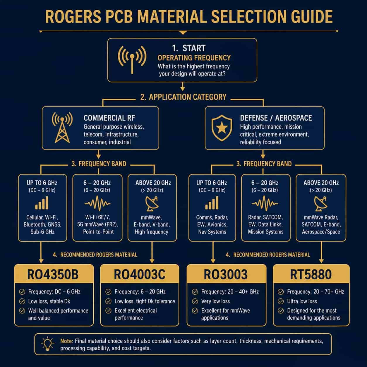
Rogers PCB material selection starts with one question: what is the operating frequency? RO4350B covers the majority of designs from L-band through X-band with proven FR4-compatible processing. RO4003C provides 27% lower Df for demanding X-band and Ku-band applications where insertion loss budget is tight. RO3003 is the standard for Ka-band, automotive 77GHz radar, and any application where Dk stability over a wide temperature range is a design requirement. RT5880 provides the absolute minimum Df for wide-band EW systems and W-band applications.
As a direct Rogers PCB factory, we hold all four core grades in production inventory and run PTFE-specific processes for RO3003 and RT5880 in-house. Submit your stackup and Gerber files for engineering review and impedance calculation before finalizing your design — our RF PCB engineering team reviews every order before production begins.