Avionics — the electronics systems aboard an aircraft — represent one of the most demanding applications for high frequency PCB. Airborne radar, navigation receivers, electronic warfare systems, communication radios, and flight management computers must all function reliably across wide temperature ranges, survive takeoff and landing vibration, operate at altitude with reduced air pressure, and continue performing after years of service with no opportunity for component-level repair in flight.
The high frequency PCB inside avionics equipment must balance RF electrical performance, environmental robustness, long service life, and traceability requirements simultaneously. Material selection, stackup design, surface finish, conformal coating, and manufacturing quality all affect whether the finished board can meet the requirements imposed by DO-160, IPC Class 3, and the applicable military or civil aviation standards.
This guide covers the high frequency PCB requirements for key avionics system types, material selection, environmental qualification, manufacturing standards, and what information to prepare before production for avionics PCB projects.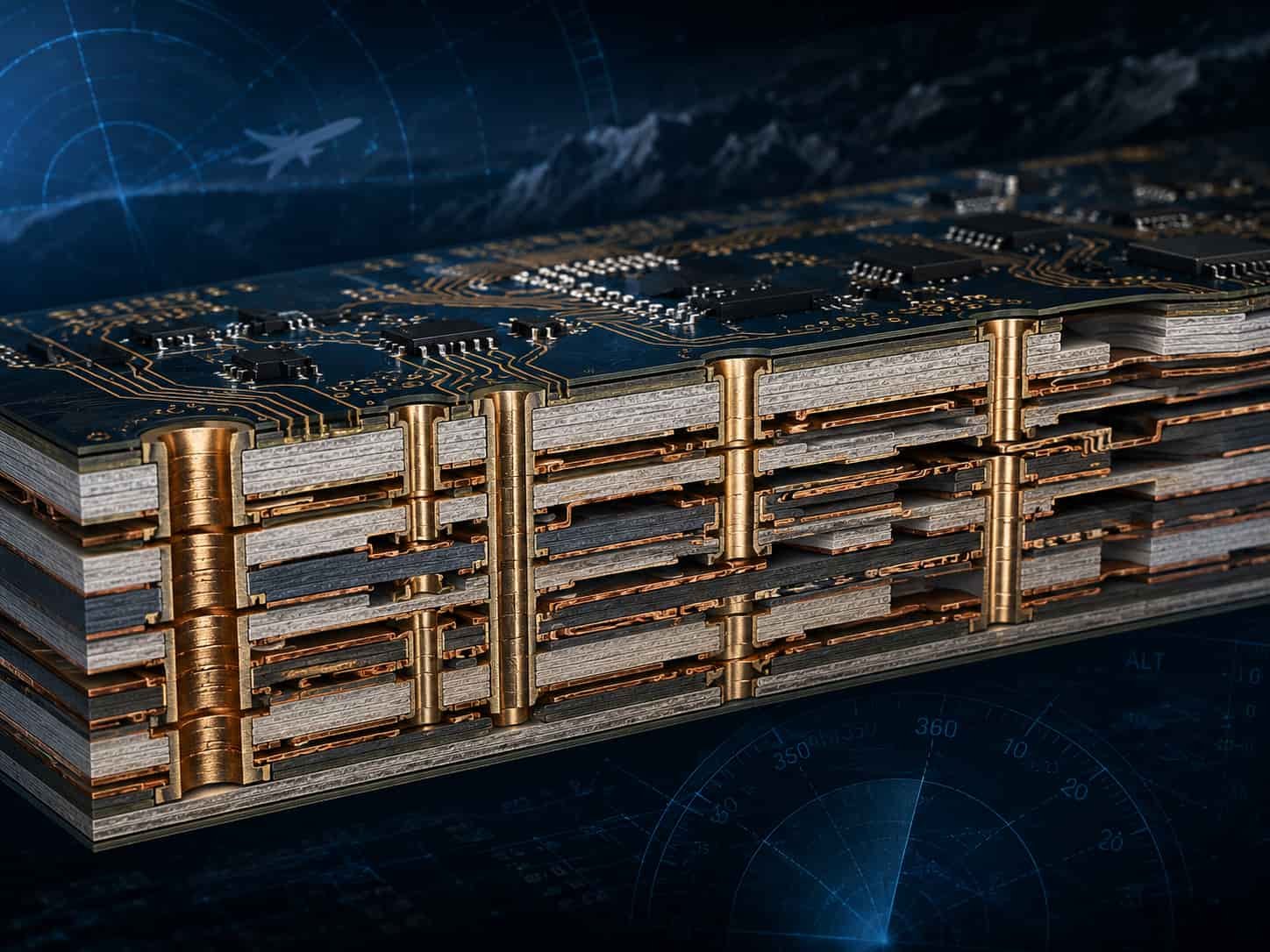
Quick Summary
Key point: Avionics high frequency PCB typically uses Rogers RO4350B for L-band to X-band applications and Rogers RO3003 or RT5880 for higher frequencies. DO-160G is the primary environmental qualification standard for civil and military avionics. IPC Class 3 is the workmanship baseline. Operating temperature range is typically -55°C to +85°C or +125°C depending on installation location. Conformal coating is standard for most avionics PCB.
The key difference between avionics PCB and general aerospace PCB is the regulatory framework — civil avionics must comply with FAA or EASA regulations and typically reference DO-160G for environmental qualification and DO-254 for hardware development assurance. Military avionics reference MIL-STD-461, MIL-STD-810, and applicable military specifications. Both paths lead to IPC Class 3 workmanship as the manufacturing baseline.
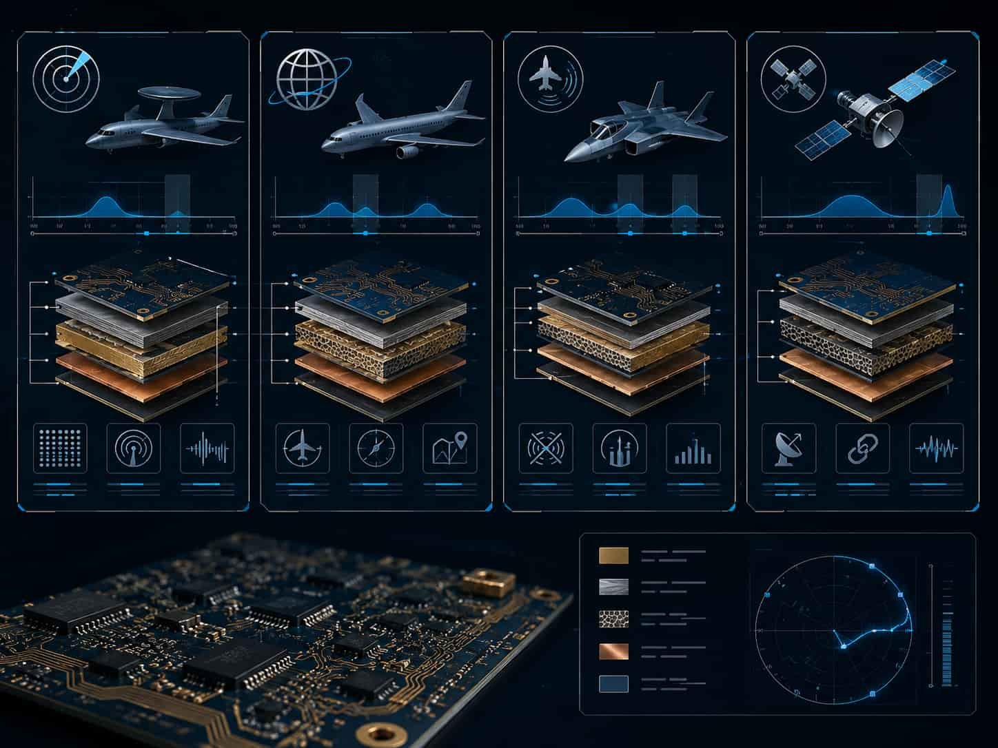
High Frequency PCB Applications in Avionics Systems
Avionics encompasses a wide range of electronic systems, each with different frequency ranges and PCB requirements. Understanding the specific system type is the starting point for correct PCB specification.
Airborne Radar
Airborne radar systems include weather radar, terrain awareness warning system (TAWS) radar, synthetic aperture radar (SAR), and fire control radar on military aircraft. Operating frequencies range from C-band for weather radar to X-band and Ka-band for fire control and SAR applications.
- Weather radar: C-band (5.4–5.9 GHz) — Rogers RO4350B or RO4003C
- Fire control radar: X-band (8–12 GHz) — Rogers RO4003C or RO3003
- SAR and targeting radar: X-band to Ka-band — Rogers RO3003
- Millimeter-wave imaging radar: Ka-band to W-band — Rogers RT5880
- All airborne radar PCB: IPC Class 3, conformal coating, DO-160 environmental qualification
Navigation and Communication
Navigation avionics includes ILS (Instrument Landing System), VOR/DME, GPS/GNSS receivers, ADS-B transponders, and radio altimeters. Communication systems include VHF/UHF radios, HF communication, and satellite communication terminals on commercial and military aircraft.
- ILS/VOR: 108–118 MHz — lower frequency, standard high-Tg FR4 or RO4350B
- Radio altimeter: 4.2–4.4 GHz — Rogers RO4350B
- GPS/GNSS: 1.176–1.575 GHz — Rogers RO4350B, antenna PCB
- ADS-B: 1090 MHz — Rogers RO4350B or high-Tg FR4
- VHF/UHF radio: 30–400 MHz — high-Tg FR4 for most power amplifier PCB
- Airborne SATCOM terminal: Ku-band or Ka-band — Rogers RO3003
Electronic Warfare
Military aircraft carry electronic warfare systems including radar warning receivers (RWR), electronic countermeasure (ECM) pods, and directed energy systems. EW systems typically must cover wide frequency ranges from 2 GHz to 18 GHz or beyond, placing demanding requirements on PCB insertion loss and Dk stability.
- Radar warning receiver: 2–18 GHz broadband — Rogers RT5880 for lowest and most stable Dk
- ECM jamming systems: matched to threat frequency range — Rogers RT5880 or RO3003
- Self-protection systems: may include laser warning and missile approach warning — mixed RF and optical
- All airborne EW PCB: IPC Class 3, full traceability, MIL-STD-461 EMC qualification
Flight Management and Avionics Computers
Flight management systems (FMS), mission computers, and avionics processing units are primarily digital systems but often include RF interfaces for navigation sensor inputs and communication links. High frequency PCB requirements apply to the RF front-end sections of these units.
- RF sections: typically L-band to S-band — Rogers RO4350B or hybrid FR4 + Rogers stackup
- Digital sections: high-speed FR4 for signal processing — hybrid stackup with Rogers on RF layers
- Wide operating temperature: -55°C to +70°C for cockpit units, -55°C to +85°C for avionics bays
DO-160G Environmental Qualification for Avionics PCB
RTCA DO-160G (Environmental Conditions and Test Procedures for Airborne Equipment) is the primary environmental qualification standard for civil avionics equipment. Military avionics typically references equivalent MIL-STD-810 and MIL-STD-461 tests. DO-160G defines test conditions for temperature, altitude, humidity, shock, vibration, explosion proofing, waterproofness, EMC, and other environmental factors.
Temperature and Altitude
DO-160G Section 4 defines temperature and altitude test categories for avionics equipment. The test category depends on the installation location in the aircraft — controlled environment (pressurized cockpit), semi-controlled (avionics bay), and uncontrolled (unpressurized compartments, external pods).
- Category A1 (controlled): -15°C to +55°C operating, -55°C to +70°C short term
- Category D1 (semi-controlled): -55°C to +70°C operating
- Category F1 (uncontrolled): -55°C to +85°C operating
- Altitude: up to 55,000 ft (16,800 m) for most avionics categories
- PCB material must maintain dielectric properties and dimensional stability across the full DO-160 temperature category
Vibration
DO-160G Section 8 defines vibration test requirements. Avionics equipment is exposed to vibration from engines, aerodynamic buffet, and landing gear operation. The PCB must be designed to withstand these vibration levels without component failure, solder joint cracking, or delamination.
- Vibration categories range from 0.01 g²/Hz to higher levels for helicopter-mounted equipment
- PCB natural frequency must be characterized — resonance within the test frequency range may require damping
- Heavy components (transformers, connectors, heat sinks) may require additional mechanical support
- Conformal coating helps retain component solder joints under vibration
Humidity and Condensation
DO-160G Section 6 defines humidity test conditions. Aircraft operate in environments ranging from dry high-altitude air to humid tropical conditions. Condensation can occur when equipment cools rapidly during descent from altitude.
- Standard humidity test: 95% RH at +40°C for 6 hours, followed by condensation test
- Conformal coating provides the primary protection against humidity effects on avionics PCB
- Rogers PTFE materials are inherently hydrophobic — lower moisture absorption than FR4
- ENIG surface finish maintains consistent RF pad performance after humidity exposure
EMC — MIL-STD-461 for Military Avionics
Military avionics must meet EMC requirements defined in MIL-STD-461. The PCB design directly affects radiated and conducted emissions, and must provide adequate shielding and filtering for the equipment to pass EMC testing.
- RE102: radiated emissions from antenna terminals — signal integrity of RF PCB affects spurious emissions
- RS103: radiated susceptibility — PCB must not malfunction under external RF fields
- CS101/CS114: conducted susceptibility — power supply filtering and decoupling on PCB
IPC Class 3 and Quality Requirements for Avionics PCB
IPC Class 3 is the baseline workmanship and acceptability standard for avionics high frequency PCB. Civil avionics programs complying with DO-254 (Design Assurance Guidance for Airborne Electronic Hardware) have additional development assurance requirements that go beyond IPC Class 3 manufacturing quality.
IPC Class 3 Manufacturing Requirements
- PTH copper plating: 25 µm average, 20 µm minimum at any point
- No annular ring breakout on any layer
- Maximum single void: 5% of hole length
- 100% electrical test: continuity and isolation for every board
- Microsection analysis: FAI required, periodic sampling during production
- Full traceability: material certificates, process records, board serialization
DO-254 Hardware Development Assurance
For civil avionics equipment certified under FAR Part 25 or equivalent regulations, DO-254 defines hardware development assurance levels (DAL A through E) based on the severity of failure consequences. PCB used in DAL A or DAL B avionics systems faces the most stringent design assurance requirements.
- DAL A (Catastrophic): failure may cause aircraft loss — highest assurance level
- DAL B (Hazardous): failure may cause serious injury or significant aircraft damage
- DAL C (Major): failure requires abnormal crew workload or impairs capabilities
- PCB design reviews, verification testing, and configuration control must be documented per DO-254
- Traceability from requirements through design to test evidence is required for DO-254 compliance
Note: DO-254 is a development assurance standard, not a manufacturing quality standard. IPC Class 3 addresses manufacturing workmanship. Both apply simultaneously to avionics PCB used in safety-critical civil aircraft systems. Military avionics follows MIL-HDBK-516 airworthiness certification requirements, which have similar development assurance obligations.
Material Selection for Avionics High Frequency PCB
Material selection for avionics PCB must balance RF electrical performance, thermal stability across the DO-160 operating temperature range, CTE compatibility for long-term thermal cycling reliability, and compatibility with conformal coating and other environmental protection processes.
Rogers RO4350B — Standard for Most Avionics RF Applications
Rogers RO4350B is the most widely used material for avionics high frequency PCB covering frequencies from L-band through X-band. Its Tg of >280°C provides excellent thermal stability across the -55°C to +85°C avionics operating range, and its hydrocarbon ceramic base is compatible with standard multilayer lamination processes.
- Frequency range: L-band to X-band (up to approximately 30–40 GHz)
- Dk: 3.48 ±0.05, Df: 0.0037 at 10 GHz
- Tg: >280°C — well above maximum avionics operating temperature
- Compatible with standard multilayer lamination — cost-effective for hybrid FR4 + Rogers stackups
- Applications: airborne weather radar, navigation receivers, VHF/UHF radio PA, ATC transponders
Rogers RO3003 — For Higher Frequency and Lower Loss Avionics
Rogers RO3003 is used for avionics applications requiring lower insertion loss or operating at frequencies above X-band. Its PTFE base provides no glass transition concern across the avionics temperature range, and its Dk temperature coefficient of +13 ppm/°C gives better electrical stability over temperature than RO4350B.
- Frequency range: X-band to Ka-band and above
- Dk: 3.0 ±0.04, Df: 0.0010 at 10 GHz
- Tg: >500°C (PTFE base) — no glass transition in avionics temperature range
- Dk temperature coefficient: +13 ppm/°C — more stable than RO4350B over temperature
- Applications: airborne fire control radar, airborne EW, Ka-band SATCOM terminals, mmWave sensors
Rogers RT5880 — EW and Millimeter-Wave Avionics
Rogers RT5880 is used in airborne EW systems and millimeter-wave avionics applications requiring the lowest possible insertion loss across a wide frequency range.
- Frequency range: wide-band EW (2–18 GHz+), W-band mmWave
- Dk: 2.2 ±0.02, Df: 0.0009 — lowest loss standard avionics PCB material
- Applications: radar warning receivers, ECM systems, millimeter-wave imaging sensors
For detailed material properties, see Rogers PCB Material Selection Guide for RF and Microwave Applications. For wide temperature range material comparison, see Wide Temperature Range PCB: Material and Manufacturing for Aerospace Applications.
Conformal Coating for Avionics High Frequency PCB
Conformal coating is standard for most avionics PCB. It provides protection against humidity, condensation, salt fog, fungal growth, and contamination from fluids that may be present in avionics bays. The coating must maintain adhesion and flexibility across the DO-160 operating temperature range without affecting RF performance of antenna pads and RF connectors.
Coating Selection for Avionics
- Acrylic (AR): most common for avionics — -65°C to +125°C, easy to rework, good humidity protection
- Polyurethane (UR): good chemical resistance — used where fuel or hydraulic fluid exposure is possible
- Silicone (SR): -65°C to +200°C — for highest temperature avionics locations near engines
- Parylene: conformal deposition process — excellent pinhole-free coverage for high reliability avionics
RF Pad and Connector Masking
RF test points, SMA and other RF connector pads, antenna pads, and any surface requiring soldering after coating must be masked before coating application. The masking specification must be defined on the assembly drawing.
- RF pad masking: dots or plugs applied before coating, removed after cure
- Connector area masking: typically 5–10 mm clearance around RF connector footprint
- Impedance test coupon: must be coated if coupon represents the production board environment
- Coating coverage documentation: photograph or AOI inspection to verify coverage and exclusion areas
Controlled Impedance for Avionics High Frequency PCB
Controlled impedance is required for all RF signal traces in avionics high frequency PCB. The impedance specification must remain within tolerance across the full DO-160 operating temperature range.
- Standard impedance tolerance: ±10% for most avionics RF PCB
- Tighter tolerance: ±5% for phased array and precision navigation antenna feed networks
- Temperature variation: must be included in worst-case analysis using material Dk temperature coefficient
- Impedance coupon: TDR measurement every production lot — results documented and retained
- Stackup must use actual Dk from material certificate — not nominal datasheet value
- Hybrid stackups: impedance calculated using confirmed Dk for each layer material
For controlled impedance background, see Why Controlled Impedance Matters in RF PCB Manufacturing. For multilayer avionics stackup design, see Multilayer High Frequency PCB: Layer Count, Stackup and Manufacturing Limits.
Traceability and Documentation for Avionics PCB
Avionics PCB requires comprehensive traceability documentation to support qualification, acceptance testing, in-service maintenance, and failure investigation. The documentation package must accompany the boards from manufacturing through the end of the aircraft’s service life.
- Material certificates: CoC for all laminates, prepregs, surface finish chemicals
- Laminate lot number: linked to each production lot and board serial number
- Process traveler: step-by-step manufacturing record with operator identification
- Inspection records: AOI, dimensional check, and visual inspection results
- Electrical test records: pass/fail for every board by serial number
- Impedance coupon measurement: TDR results linked to production lot
- FAI report: microsection, plating thickness, surface finish measurement results
- Configuration identification: PCB part number, revision, and date code on every board
- Record retention: minimum aircraft design life — typically 30 years for commercial aircraft, program life for military
Note: For civil avionics programs under DO-254, configuration management and traceability requirements are defined by the development assurance level and the avionics certification plan. The PCB manufacturer must be informed of DO-254 applicability at the start of the program so that appropriate records are established from the first prototype lot.
Information Needed for Avionics High Frequency PCB Quotation
To review feasibility and provide an accurate quotation for avionics high frequency PCB, the following information should be prepared:
- Gerber files (all layers) and NC drill files
- Complete PCB stackup with material specification, layer sequence, and copper weight
- Avionics system type — radar, navigation, EW, communication, or flight management
- Operating frequency range
- Material specification — Rogers grade or equivalent
- DO-160G environmental category — temperature category and installation location
- IPC Class requirement — Class 3 for avionics
- DO-254 applicability and hardware development assurance level if applicable
- Controlled impedance requirements — target, tolerance, temperature range
- Via structure — through-hole, blind, buried
- Conformal coating requirement — type, coverage, and masking requirements
- Surface finish and thickness specification
- Traceability requirements — material certificates, serialization, record retention
- Applicable standards — DO-160G, MIL-STD-810, MIL-STD-461, MIL-PRF-31032
- Quantity — prototype, qualification, or production lot
For a complete file checklist, see What Files Are Needed for a High Frequency PCB Quotation?.

Conclusion
Avionics high frequency PCB covers a wide range of airborne systems from weather radar and navigation receivers at lower frequencies to airborne EW and fire control radar at X-band and Ka-band. Rogers RO4350B covers most L-band to X-band avionics applications. Rogers RO3003 and RT5880 address higher frequency and lowest loss requirements including Ka-band SATCOM terminals, airborne EW systems, and millimeter-wave sensors.
DO-160G environmental qualification, IPC Class 3 workmanship, conformal coating, full traceability, and DO-254 compliance for civil safety-critical avionics are the framework within which high frequency PCB for avionics must be designed and manufactured. Early engagement with a manufacturer experienced in avionics PCB requirements reduces qualification risk, supports program schedule, and ensures that manufacturing documentation meets the needs of the certification and maintenance program.