Mixed laminate PCB — also called hybrid PCB or heterogeneous laminate PCB — combines two or more different dielectric materials in the same multilayer board. The most common combination is Rogers high frequency material on the RF signal layers and standard FR4 on the digital, power, and structural layers. This approach allows engineers to use the optimal material for each functional section of the board without paying for premium Rogers material throughout the entire stackup.
Mixed laminate construction is widely used in aerospace radar systems, defense electronics, telecommunications equipment, and industrial RF modules where the board must support both high frequency RF circuits and conventional digital or power electronics. Understanding how FR4 and Rogers PCB materials are combined in production — and what constraints this places on the design — is essential for anyone specifying or purchasing high frequency PCB with hybrid stackups.
This guide covers the manufacturing process for mixed laminate PCB, bonding film selection, CTE mismatch management, lamination sequence, impedance planning across material boundaries, warpage control, and what information to confirm before production.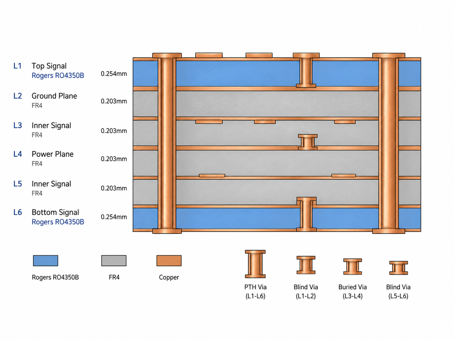
Quick Summary
Key point: Mixed laminate PCB places Rogers or PTFE material only on layers where high frequency performance is required, and uses FR4 on the remaining layers. The key production challenges are bonding film compatibility between materials, CTE mismatch management to control warpage, lamination sequence planning, and impedance calculation across material boundaries. Maximum lamination cycles follow the more restrictive material limit — if PTFE is included, the 2-cycle limit applies to the entire stackup.
Mixed laminate PCB is not simply a matter of stacking different materials in a press. Material compatibility, bonding film selection, thermal expansion matching, lamination profile optimization, and impedance transition design must all be reviewed before production begins. Designs that skip this review frequently result in delamination, warpage, or impedance inconsistency.
Why Mixed Laminate PCB Is Used
The primary reason for using mixed laminate construction is cost optimization without sacrificing RF performance. Rogers and PTFE materials are significantly more expensive than FR4. In a typical 8-layer PCB where only the top and bottom layers carry RF signals, using Rogers material on all 8 layers adds unnecessary cost for the 6 layers that do not need low-loss dielectric.
Cost Comparison
- Full Rogers RO4350B 8-layer board: Rogers material on all layers — highest cost
- Mixed laminate 8-layer board: Rogers on 2 outer RF layers, FR4 on 6 inner layers — typically 30–50% lower material cost
- Cost saving depends on layer count, board area, and Rogers material grade specified
- Engineering and process complexity of mixed laminate adds some cost back — net saving is typically 20–40%
When Mixed Laminate Is the Right Choice
- Board has distinct RF and digital/power functional sections that can be assigned to separate layer groups
- RF operating frequency is below Ka-band — Rogers RO4350B or RO4003C on RF layers is adequate
- Board thickness or layer count requirement is compatible with the hybrid stackup
- CTE mismatch between materials can be managed within the warpage tolerance for the application
- Lamination count stays within the material limits (maximum 2 cycles for PTFE, 3 for Rogers hydrocarbon)
When Full Rogers Construction Is Better
- Frequency above Ka-band — all layers need low-loss material for consistent electrical behavior
- Very thin board where the additional complexity of hybrid lamination increases risk
- Application requires outgassing qualification (space) — all layers must use space-qualified material
- Tight warpage tolerance that cannot be met with mismatched CTE materials
- Simple 2-layer or 4-layer board where material cost difference is small
Common Material Combinations in Mixed Laminate PCB
The most widely used material combinations for mixed laminate high frequency PCB are listed below. Each combination has different compatibility requirements, bonding film needs, and manufacturing constraints.
Rogers RO4350B + FR4
The most common mixed laminate combination for defense and commercial RF PCB up to X-band. Rogers RO4350B has CTE values and thermal processing requirements that are relatively compatible with FR4. Bondply such as Rogers RO4450F or RO4450T is used as the bonding film between Rogers and FR4 layers.
- Compatibility: good — RO4350B designed to be compatible with FR4 processing
- Bonding film: Rogers RO4450F bondply (Dk 3.52) or RO4450T — matches RO4350B Dk closely
- CTE match: RO4350B z-axis CTE 32–46 ppm/°C vs FR4 z-axis CTE 50–70 ppm/°C — moderate mismatch
- Lamination: compatible with standard FR4 lamination temperature and pressure
- Applications: airborne radar, defense communication, satellite ground terminal PCB up to Ku-band
Rogers RO4003C + FR4
Rogers RO4003C with FR4 is used for applications requiring lower Df than RO4350B while maintaining compatibility with FR4 processing. RO4003C has slightly different CTE values than RO4350B but similar lamination compatibility.
- Compatibility: good — similar processing requirements to RO4350B hybrid
- Bonding film: Rogers RO4450F bondply or compatible FR4 prepreg
- Applications: X-band radar PCB, lower-loss Ku-band designs, high-speed digital with RF
Rogers RO3003 + FR4
RO3003 is a PTFE material and has more demanding hybrid compatibility requirements than RO4350B. Its CTE (x-y 17 ppm/°C) is lower than FR4, requiring careful warpage management. Specialized bondply is required between PTFE and FR4 layers.
- Compatibility: more challenging than RO4350B hybrid — requires special bonding film
- Bonding film: Rogers 2929 bondply or specialized PTFE-to-FR4 adhesive film
- Lamination: separate lamination cycle for PTFE layers before combining with FR4
- Lamination cycle limit: 2 cycles maximum due to PTFE content
- Applications: Ka-band radar PCB with cost-sensitive digital sections, defense AESA with FR4 digital layers
Rogers RT5880 + FR4
RT5880 with FR4 is used for the highest-performance EW and mmWave applications that still need cost-effective digital layers. RT5880 is the most challenging PTFE material for hybrid construction due to its high z-axis CTE (237 ppm/°C) and specialized bonding requirements.
- Compatibility: challenging — highest CTE mismatch with FR4
- Bonding film: specialized RT5880-compatible bonding film — not standard FR4 prepreg
- Warpage risk: highest of common combinations — detailed thermal analysis required
- Lamination cycle limit: 2 cycles maximum
- Applications: wide-band EW PCB with FR4 digital signal processing layers
Bonding Film Selection for Mixed Laminate PCB
Bonding film — also called bondply or prepreg adhesive — is the critical interface material between Rogers and FR4 layers in a mixed laminate PCB. It must provide reliable adhesion between the two materials, have Dk and Df values compatible with the impedance design on adjacent layers, and survive the lamination temperature and pressure without degrading either material.
Rogers RO4450 Bondply Series
The Rogers RO4450 series bondply is designed specifically for bonding RO4350B and RO4003C layers to each other or to FR4. It provides consistent Dk close to the Rogers material it is bonding, ensuring minimal impedance discontinuity at the material interface.
- RO4450F: Dk 3.52 at 10 GHz — compatible with RO4350B (Dk 3.48) and RO4003C (Dk 3.38)
- RO4450T: similar properties, different filler system for specific applications
- Available thicknesses: 0.055 mm to 0.168 mm — range allows stackup thickness adjustment
- Lamination temperature: compatible with standard FR4 press cycle — simplifies hybrid processing
- Do not use standard FR4 prepreg as bondply between Rogers and FR4 — Dk mismatch causes impedance error at interface
PTFE-Compatible Bonding Films
Rogers PTFE materials (RO3003, RT5880) cannot be bonded using standard FR4 prepreg or even RO4450 bondply. Specialized bonding films designed for PTFE-to-FR4 interfaces are required.
- Rogers 2929 bondply: designed for bonding Rogers PTFE materials — low Dk, low Df
- Alternative: LD621 or similar low-flow bondply films for PTFE hybrid applications
- Bonding temperature: PTFE bonding requires different temperature profile than FR4 — must be confirmed with material supplier
- Surface preparation: PTFE surface may require sodium or plasma activation before bonding — same as for via plating
Why Standard FR4 Prepreg Cannot Be Used as Bondply
Standard FR4 prepreg (7628, 2116, 1080) has Dk of approximately 4.0–4.5 at microwave frequencies — significantly higher than Rogers materials (Dk 2.2–3.5). If FR4 prepreg is used as the bonding layer between Rogers sheets, the Dk discontinuity at the interface creates an impedance step that cannot be fully compensated by adjusting trace width alone. For all but the lowest frequency applications, the correct bondply must be used.
- FR4 prepreg Dk: 4.0–4.5 at 1 GHz — creates impedance discontinuity at Rogers interface
- Effect: reflection at material interface, standing wave formation, degraded return loss
- Severity increases with frequency — minor effect at L-band, significant at X-band and above
- Solution: always use Rogers-specified bondply for the specific Rogers material in use
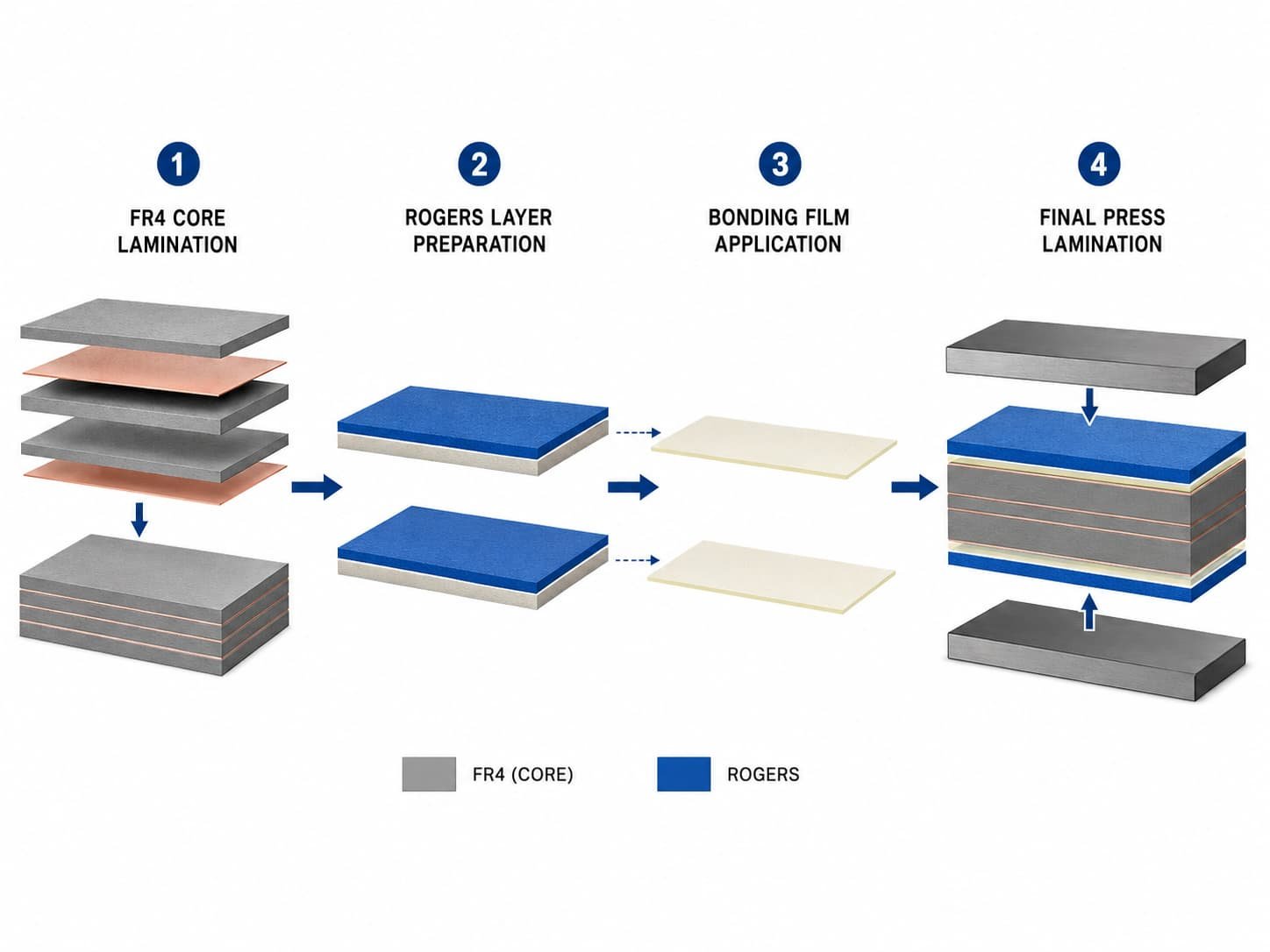
Lamination Sequence for Mixed Laminate PCB
The lamination sequence — the order in which material layers are assembled and pressed — is critical for mixed laminate PCB. The sequence must be planned to minimize the number of press cycles, keep each press cycle within the temperature and pressure limits of all materials involved, and achieve the required layer registration accuracy.
Typical 6-Layer Mixed Laminate Sequence
A typical 6-layer mixed laminate PCB with Rogers on outer layers and FR4 on inner layers is built in two press cycles:
- Press cycle 1: laminate FR4 core (layers 3 and 4) with FR4 prepreg — standard FR4 process
- After press 1: drill and plate inner layer vias if blind vias connect FR4 layers
- Press cycle 2: add Rogers outer layers (layers 1-2 and 5-6) with Rogers bondply on each side — full stack lamination
- After press 2: drill and plate through-hole vias, process outer layers
- Total: 2 press cycles — within the 3-cycle limit for FR4 and the 2-cycle limit for Rogers hydrocarbon
Layer Sequence Constraints
- PTFE-containing stackups limited to 2 press cycles total
- FR4-only cores can be pre-laminated before Rogers layers are added — reduces thermal exposure of Rogers material
- Blind vias in FR4 layers must be processed in press cycle 1 before Rogers layers are added
- Registration accuracy: each press cycle introduces potential for layer shift — more cycles mean more registration tolerance
- Symmetry: the stackup above and below the center must be symmetric to minimize warpage
Design tip: For mixed laminate PCB with blind vias in both Rogers and FR4 sections, the lamination sequence quickly becomes complex. The number of press cycles and via types must be mapped out as a sequence diagram before design finalization. A manufacturer review of the via structure and lamination sequence before tapeout prevents expensive redesign.
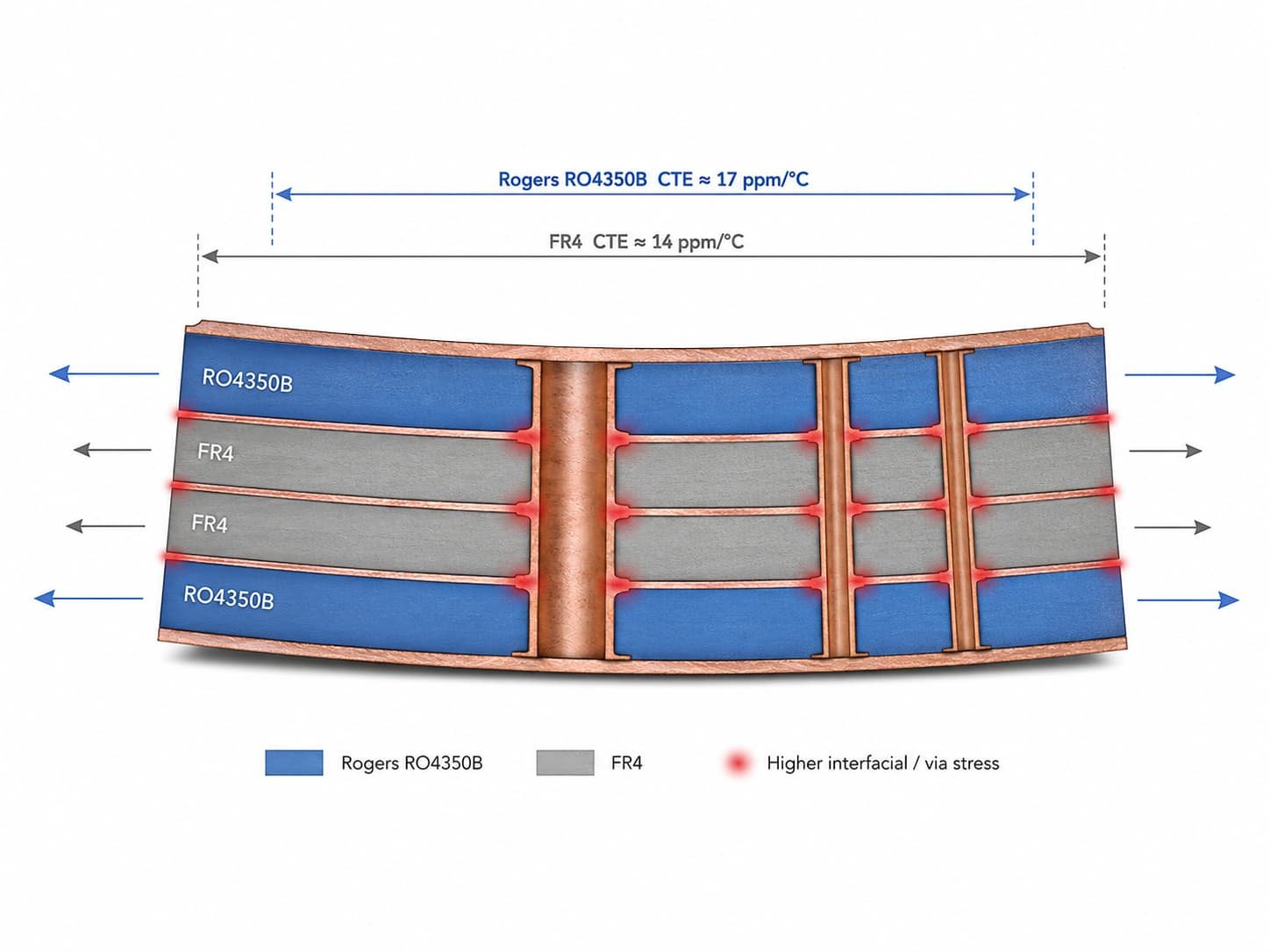
CTE Mismatch and Warpage Control in Mixed Laminate PCB
CTE mismatch between Rogers and FR4 materials is the primary source of warpage in mixed laminate PCB. Because the two materials expand at different rates when heated during lamination and then contract at different rates when cooled, the finished board may bow or twist.
CTE Values for Common Mixed Laminate Materials
- Rogers RO4350B x-y CTE: 14–17 ppm/°C
- Rogers RO3003 x-y CTE: 17 ppm/°C
- Rogers RT5880 x-y CTE: 31 ppm/°C
- Standard FR4 x-y CTE: 14–17 ppm/°C — matches RO4350B and RO3003 closely in x-y plane
- CTE mismatch in z-axis: more significant — Rogers z-axis CTE 24–46 ppm/°C vs FR4 50–70 ppm/°C
- RT5880 z-axis CTE: 237 ppm/°C — very high mismatch with FR4 in z-axis
Warpage Management Strategies
- Symmetric stackup: equal Rogers material thickness above and below the board center — minimizes net bending moment
- Copper balance: same copper weight and fill percentage on corresponding layers above and below center
- Minimize Rogers layer thickness difference from FR4 layers — closer thickness means less CTE-driven bending
- Press profile optimization: slow cooling rate reduces residual stress from CTE mismatch
- Warpage specification: IPC standard ≤ 0.75% for SMT boards — confirm this is achievable before design is released
Controlled Impedance Across Material Boundaries
In a mixed laminate PCB, controlled impedance traces on Rogers layers must transition to the FR4 section of the stackup at some point — either at a via or at a layer transition in the routing. The impedance on each layer must be calculated using the actual Dk of that layer’s dielectric material, not an average or assumed value.
Impedance Calculation by Layer
- Rogers layers: use Rogers material Dk for impedance calculation — e.g. RO4350B Dk 3.48
- FR4 layers: use FR4 prepreg Dk for impedance calculation — typically 3.8–4.2 at operating frequency
- Bondply layers: use bondply Dk — Rogers RO4450F Dk 3.52 at 10 GHz
- Each layer may have a different minimum trace width for the same impedance target
- Impedance calculation must use the confirmed production Dk values — not nominal datasheet values
Via Transitions Between Rogers and FR4 Layers
When an RF signal transitions from a Rogers layer to an FR4 layer through a via, the via introduces an impedance discontinuity because the dielectric surrounding the via barrel changes from Rogers to FR4. For low frequencies this is typically acceptable. At X-band and above, via transition design must minimize the reflection.
- Via size: smaller via diameter reduces via capacitance and inductance at the transition
- Anti-pad: clearance around the via in ground planes affects via capacitance — must be sized correctly
- Back drill: for through-hole vias transitioning between Rogers and FR4, back drilling removes the via stub in the section not carrying the signal
- Blind via: if design allows, use blind vias that terminate at the interface layer — no stub
For via transition design, see Via Design Considerations for RF PCB Manufacturing. For back drill stub removal, see Back Drill PCB: What It Is, When You Need It, and Manufacturing Limits.
Impedance Verification for Mixed Laminate PCB
Impedance coupon design for mixed laminate PCB must include coupons on both Rogers layers and FR4 layers to verify impedance independently on each material section. A single coupon on only one material does not verify the other material’s impedance.
- Rogers layer coupon: placed on the panel edge on Rogers outer layers — verifies RF signal layer impedance
- FR4 layer coupon: placed on corresponding FR4 layers if impedance-controlled traces run on inner FR4 layers
- Coupon trace geometry: must match the actual signal trace width, dielectric thickness, and ground plane arrangement
- TDR measurement: both coupons measured separately — results linked to the production lot
- Impedance tolerance: ±10% standard for both Rogers and FR4 sections
For controlled impedance background, see Why Controlled Impedance Matters in RF PCB Manufacturing. For full stackup planning, see RF PCB Stackup Design: Key Factors Before Manufacturing.
Manufacturing Constraints for Mixed Laminate PCB
Lamination Cycle Limits
- FR4 + Rogers RO4350B or RO4003C: maximum 3 lamination cycles — governed by FR4 limit
- FR4 + Rogers RO3003 or RT5880: maximum 2 lamination cycles — governed by PTFE limit
- Each additional blind via stage requires one more lamination cycle — quickly reaches the limit
- Through-hole only designs: typically 2 cycles regardless of material — FR4 core press + Rogers outer press
Drill and Plate Constraints
- PTFE layers in the stackup require sodium or plasma hole wall activation before copper plating — same as pure PTFE boards
- FR4 layers use standard desmear process — different chemistry from PTFE activation
- If PTFE and FR4 layers are in the same panel at the time of drilling, the via plating process must accommodate both material types
- Drill parameters: may need to be adjusted for the combination of materials — standard FR4 drill parameters may not be optimal for Rogers layers
Warpage After Assembly
- Mixed laminate boards may bow slightly more than same-material boards after solder reflow due to CTE mismatch
- IPC warpage limit: ≤ 0.75% for SMT boards — must be verified on first article
- Component placement: sensitive fine-pitch components may be affected by warpage — placement on flattest region preferred
- Fixturing during reflow: use reflow carriers or pallets for boards with known warpage tendency
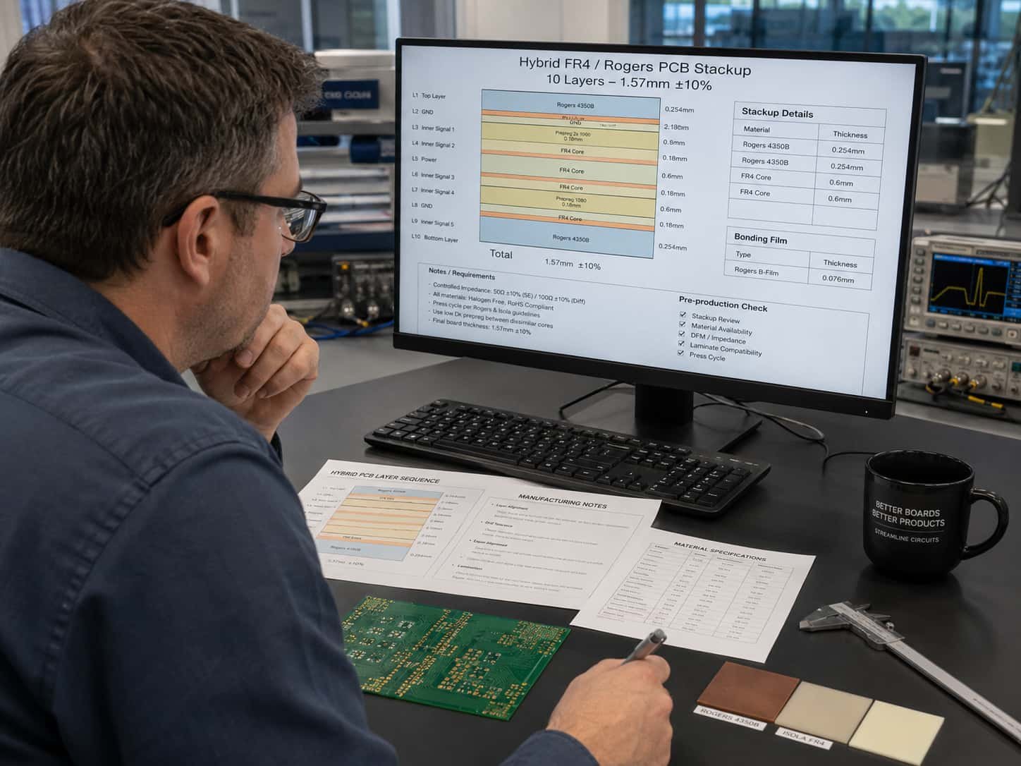
Information Needed for Mixed Laminate PCB Quotation
To review feasibility and provide an accurate quotation for mixed laminate FR4 + Rogers PCB, the following information should be prepared:
- Gerber files (all layers) and NC drill files
- Complete PCB stackup with layer sequence, material type for each layer, dielectric thickness, and copper weight
- Identification of Rogers layers and FR4 layers in the stackup
- Bonding film specification — or request for manufacturer recommendation
- Via structure — through-hole, blind, buried — with layer connections defined
- Controlled impedance requirements for Rogers layers and FR4 layers separately
- Operating frequency range
- Warpage tolerance requirement
- IPC Class requirement — Class 2 or Class 3
- Surface finish and thickness specification
- Traceability requirements
- Quantity — prototype or production lot
For a complete file checklist, see What Files Are Needed for a High Frequency PCB Quotation?. For multilayer design considerations, see Multilayer High Frequency PCB: Layer Count, Stackup and Manufacturing Limits.
Conclusion
Mixed laminate PCB combining FR4 and Rogers materials is a cost-effective approach for designs where only certain layers require high frequency performance. Rogers RO4350B with FR4 is the most common and most manufacturing-friendly combination. PTFE-based Rogers materials (RO3003, RT5880) with FR4 are more challenging and require specialized bonding films, two-cycle lamination limits, and careful warpage management.
Successful mixed laminate high frequency PCB production requires early engagement on bonding film selection, lamination sequence planning, impedance calculation by layer, CTE mismatch analysis, and warpage control. Submitting a complete stackup with all layer materials clearly identified — before Gerber files are finalized — is the most effective way to reduce production risk and avoid costly design revisions.