
Rogers RO4003C PCB: Lower Loss Alternative to RO4350B for X-Band and Ku-Band
Rogers RO4003C uses the same FR4-compatible process as RO4350B with 27% lower Df (0.0027 vs 0.0037). The right choice for X-band radar, Ku-band satellite and any application above 8 GHz where insertion loss budget is tight.
Home » High Frequency PCB » Rogers RO4003C PCB: Lower Loss Alternative to RO4350B for X-Band and Ku-Band
Table of Contents
Key point: Rogers RO4003C (Dk 3.38, Df 0.0027) uses the same FR4-compatible process as RO4350B — no plasma activation, same 5–7 day lead time — with 27% lower Df. At 10 GHz the insertion loss advantage is ~0.16 dB/cm; at 18 GHz ~0.30 dB/cm. A Ku-band feed network spanning 15 cm saves approximately 0.9 dB vs RO4350B. Available thicknesses: 0.203 / 0.305 / 0.406 / 0.508 / 0.813 / 1.524 mm — no 0.101 mm or 0.168 mm (use RO4350B for those). Material cost ~20–30% higher than RO4350B. Riching PCB stocks RO4003C in all standard thicknesses. No MOQ. Prototype 5–7 working days.
Rogers RO4003C is the lower-loss member of the RO4000 hydrocarbon ceramic family. It shares identical manufacturing process with RO4350B — same drill parameters, same lamination cycle, same surface finish options, no plasma activation required — while offering Df of 0.0027 vs RO4350B’s 0.0037. That 27% Df reduction becomes a meaningful performance advantage at X-band (8–12 GHz) and above, where insertion loss per unit length is high enough that the difference accumulates to 1–2 dB over typical trace lengths.
This guide covers RO4003C material properties, available thicknesses, 50Ω trace width reference, the specific scenarios where RO4003C outperforms RO4350B, and applications.
RO4003C Material Properties
| Property | Value | Test Condition |
|---|---|---|
| Dielectric Constant (Dk) | 3.38 ± 0.05 | 10 GHz, IPC-TM-650 2.5.5.5 |
| Dissipation Factor (Df) | 0.0027 — 27% lower than RO4350B | 10 GHz, IPC-TM-650 2.5.5.5 |
| TCDk | +40 ppm/°C | –50 to +150°C |
| Thermal Conductivity | 0.64 W/m/K | ASTM C518 |
| CTE (x, y axis) | 11 ppm/°C | IPC-TM-650 2.4.41 |
| Tg | >280°C | TMA |
| Flame Retardant | UL 94 V-0 | — |
| Process Type | FR4-compatible — no plasma activation required | — |
| Available Thicknesses (mm) | 0.203 / 0.305 / 0.406 / 0.508 / 0.813 / 1.524 | — |
When Does the Lower Df Actually Matter
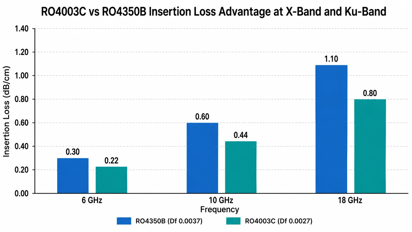
The insertion loss advantage of RO4003C over RO4350B scales with frequency:
- At 1 GHz: ~0.02 dB/cm difference — negligible
- At 6 GHz: ~0.08 dB/cm difference — marginal for most designs
- At 10 GHz: ~0.16 dB/cm difference — meaningful over traces longer than 5 cm
- At 18 GHz: ~0.30 dB/cm difference — significant for Ku-band satellite feed networks
The practical threshold: if your design operates above 8 GHz and has RF trace lengths exceeding 5 cm, RO4003C provides a measurable insertion loss improvement. For designs below 6 GHz or with short traces, RO4350B is more cost-effective.
A specific example: a Ku-band VSAT terminal antenna feed network spanning 15 cm at 14 GHz. On RO4350B: approximately 3.3 dB insertion loss. On RO4003C: approximately 2.4 dB — a 0.9 dB improvement that may be the difference between meeting and failing the link budget.
RO4003C vs RO4350B: Key Differences
- Df: 0.0027 vs 0.0037 — 27% lower for RO4003C
- Dk: 3.38 vs 3.48 — RO4003C slightly lower, producing slightly wider traces for same impedance
- Thicknesses: RO4003C 6 options (0.203–1.524 mm) vs RO4350B 8 options (0.101–1.524 mm)
- No 0.101 mm or 0.168 mm in RO4003C — rules it out for Ka-band and mmWave thin substrate designs
- Material cost: RO4003C approximately 20–30% higher per panel than RO4350B
- Lead time and process: identical — 5–7 working days prototype, no plasma activation
For a detailed head-to-head comparison, see RO4350B vs RO4003C comparison guide.
Available Thicknesses and 50Ω Microstrip Trace Widths
RO4003C standard dielectric thicknesses: 0.203 mm / 0.305 mm / 0.406 mm / 0.508 mm / 0.813 mm / 1.524 mm
| Core Thickness | Copper Weight | 50Ω Microstrip Width (approx.) | Typical Application |
|---|---|---|---|
| 0.203 mm | 0.5 oz | ~0.43 mm | X-band, thin substrate designs |
| 0.305 mm | 1 oz | ~0.66 mm | X-band radar, Ku-band |
| 0.406 mm | 1 oz | ~0.88 mm | Ku-band satellite terminal |
| 0.508 mm | 1 oz | ~1.10 mm | Ku-band, general RF 6–18 GHz |
| 0.813 mm | 1 oz | ~1.77 mm | Lower frequency, power amplifier |
| 1.524 mm | 1 oz | ~3.33 mm | Lower frequency RF applications |
Approximate values. Confirm with fabricator using production Dk from material certificate.
For X-band (8–12 GHz) designs, 0.305 mm is the most common thickness — it provides a 50Ω trace width of approximately 0.66 mm, wide enough for reliable etching while keeping the substrate thin enough for good microstrip performance. For Ku-band (12–18 GHz) satellite terminals, 0.406 mm or 0.508 mm are standard.
Manufacturing: FR4-Compatible, No Plasma Required
RO4003C and RO4350B are both hydrocarbon ceramic laminates. They process on standard FR4-compatible equipment with no special process requirements:
- No plasma activation — unlike RO3003, RT5880 and other PTFE materials
- Standard FR4 drill parameters — no reduced spindle speed required
- Standard FR4 press cycle — no lamination cycle limit
- Rogers 4450F bondply for FR4 hybrid stackups — same as RO4350B
- Prototype lead time: 5–7 working days — same as RO4350B
This means any factory capable of manufacturing RO4350B can manufacture RO4003C without any process change, equipment upgrade, or lead time increase. The only difference is material cost.
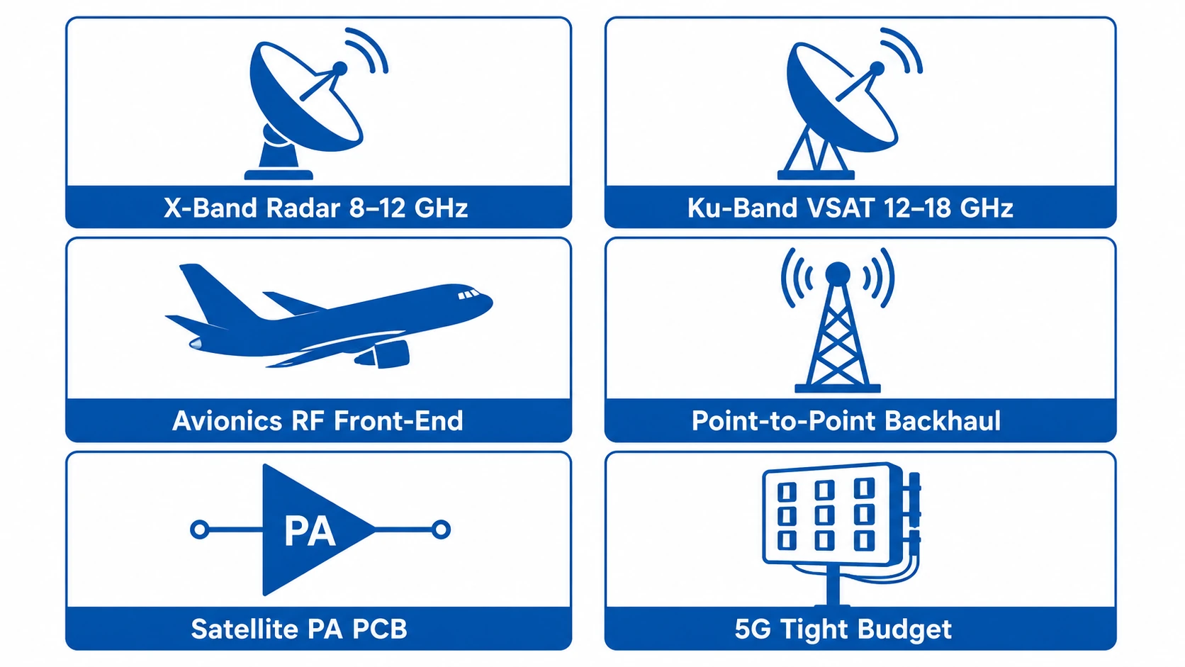
Applications
| Application | Frequency | Why RO4003C over RO4350B |
|---|---|---|
| X-band radar | 8–12 GHz | 0.16 dB/cm less loss — meaningful over 10+ cm traces |
| Ku-band VSAT terminal | 12–18 GHz | Long antenna feed networks — 0.30 dB/cm advantage at 18 GHz |
| Satellite uplink amplifier | 14–14.5 GHz | Tight efficiency budget — every dB matters |
| Point-to-point backhaul | 6–18 GHz | Long traces in flat panel antenna arrays |
| Avionics RF front-end | 8–18 GHz | Lower loss reduces thermal stress in Class 3 designs |
| 5G sub-6GHz tight budget | 3.3–5.0 GHz | Only if link budget analysis shows RO4350B is marginal |
When to Use RO4003C vs Other Rogers Materials
- Use RO4350Bwhen: frequency below 6 GHz, insertion loss budget comfortable, or cost is the priority
- Use RO4003C when: frequency 8–18 GHz, insertion loss budget is tight, traces longer than 5 cm
- Use RO3003when: frequency above 20 GHz (Ka-band, 77 GHz) — both RO4000 series materials are insufficient above 20 GHz
- Use RT5880when: wideband 2–18 GHz EW applications or absolute minimum insertion loss is required
Conclusion
Rogers RO4003C (Dk 3.38, Df 0.0027) is the lower-loss hydrocarbon ceramic alternative to RO4350B — same FR4-compatible process, same 5–7 day lead time, 27% lower Df. The material cost premium of 20–30% over RO4350B is justified for X-band (8–12 GHz) and Ku-band (12–18 GHz) designs where trace lengths exceed 5 cm and insertion loss budget is tight. For applications below 6 GHz, RO4350B is the more cost-effective choice. For applications above 20 GHz, PTFE materials (RO3003, RT5880) are required. Riching PCB stocks RO4003C in all standard thicknesses. No MOQ. Prototype 5–7 working days. See Rogers materials overview for full thickness availability.
Get a Quote for Rogers RO4003C PCB
All standard thicknesses in stock. Same 5–7 day lead time as RO4350B. Send the following:
- Gerber files + NC drill file
- RO4003C dielectric thickness
- Copper weight per layer
- Controlled impedance requirements
- Operating frequency and application
- Quantity and IPC Class
WhatsApp +86 13760473650 — quotation within 4–8 hours
Rogers RO4003C PCB Q&A
Common questions about Rogers RO4003C applications, differences from RO4350B, plasma activation, available thicknesses and when to upgrade from RO4350B.
What is Rogers RO4003C used for?
X-band radar (8–12 GHz), Ku-band satellite terminals (12–18 GHz), point-to-point microwave backhaul, avionics RF front-end, and 5G sub-6GHz tight-budget designs. 27% lower Df than RO4350B, same FR4-compatible process.
What is the difference between RO4003C and RO4350B?
Df 0.0027 vs 0.0037 (27% lower), Dk 3.38 vs 3.48, both FR4-compatible no plasma, same 5–7 day lead time. RO4003C 20–30% higher material cost, fewer thickness options (no 0.101 or 0.168 mm).
Does RO4003C require plasma activation?
No — hydrocarbon ceramic, same as RO4350B. FR4-compatible process, no plasma, no special drill parameters. Lead time identical to RO4350B: 5–7 working days.
What thicknesses are available for Rogers RO4003C?
0.203 / 0.305 / 0.406 / 0.508 / 0.813 / 1.524 mm. No 0.101 mm or 0.168 mm — use RO4350B for those. For X-band: 0.305 mm standard. For Ku-band: 0.406 or 0.508 mm.
When should I choose RO4003C over RO4350B?
Above 8 GHz with traces >5 cm and tight insertion loss budget. At 10 GHz: ~0.16 dB/cm less loss. At 18 GHz: ~0.30 dB/cm less. A 15 cm Ku-band feed network saves ~0.9 dB vs RO4350B. Below 6 GHz: RO4350B better cost-performance.
Request a PCB Quote
Upload your Gerber ZIP file and project requirements. Our engineering team will review your PCB material, stackup, impedance needs, surface finish, and production quantity before quoting.
Please prepare:
- Gerber files in ZIP format
- PCB material or stackup requirements
- Controlled impedance notes if available
- Prototype or batch production quantity
