Rogers RO3003 PCB: Material Properties, Applications and Manufacturing Guide
Complete guide to Rogers RO3003 PTFE ceramic substrate — Dk 3.0, Df 0.0010. Standard material for Ka-band satellite, 77 GHz automotive radar and 5G mmWave phased arrays. Available thicknesses, 50Ω trace widths and plasma activation requirements.
Home » 77 GHz radar PCB material » Rogers RO3003 PCB: Material Properties, Applications and Manufacturing Guide
Table of Contents
Key point: Most factories quote 3–4 weeks waiting for RO3003 / RT5880 material procurement. Riching PCB maintains these materials in stock — no material wait. Rogers RO3003 is a PTFE ceramic substrate with Dk 3.0 and Df 0.0010 — standard for Ka-band (26.5–40 GHz), 77 GHz automotive radar and 5G mmWave 28 GHz phased arrays. At 30 GHz, RO3003 insertion loss is ~0.5 dB/cm vs ~1.8 dB/cm for RO4350B. 50Ω microstrip on 0.127 mm RO3003 with 0.5 oz copper: ~0.28 mm trace width. Available thicknesses: 0.127 / 0.254 / 0.508 / 0.762 / 1.524 mm. All RO3003 orders require in-house plasma hole wall activation and maximum 2 lamination press cycles. Riching PCB stocks RO3003 in 0.127 mm and 0.254 mm with in-house plasma activation. No MOQ. Prototype 7–10 working days.
Rogers RO3003 is the standard PTFE ceramic substrate for Ka-band (26.5–40 GHz), 77 GHz automotive radar, and 5G mmWave phased array PCB. Its combination of low Df (0.0010), stable Dk (3.0 ± 0.04), and better thermal conductivity than PTFE glass materials makes it the most widely used substrate in the 20–80 GHz frequency range. Unlike Rogers RO4350B, RO3003 is PTFE-based — it requires in-house plasma hole wall activation before copper plating.
This guide covers RO3003 material properties, available thicknesses, 50Ω microstrip trace widths, comparison with RT5880 and RO4350B, manufacturing requirements, and applications.
RO3003 Material Properties
| Property | Value | Test Condition |
|---|---|---|
| Dielectric Constant (Dk) | 3.0 ± 0.04 | 10 GHz, IPC-TM-650 2.5.5.5 |
| Dissipation Factor (Df) | 0.0010 | 10 GHz, IPC-TM-650 2.5.5.5 |
| TCDk | +13 ppm/°C | –50 to +150°C |
| Thermal Conductivity | 0.50 W/m/K | ASTM C518 |
| CTE (x, y axis) | 17 ppm/°C | IPC-TM-650 2.4.41 |
| CTE (z axis) | 24 ppm/°C | IPC-TM-650 2.4.41 |
| Tg | >500°C (PTFE) | — |
| Flame Retardant | UL 94 V-0 | — |
| Process Type | PTFE ceramic — plasma activation required | — |
RO3003 vs RO4350B: Why PTFE Is Needed Above 20 GHz
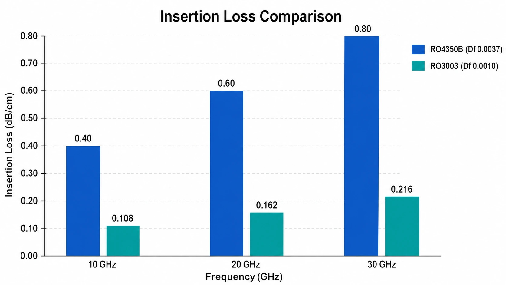
RO4350B (Df 0.0037) produces approximately 0.6 dB/cm insertion loss at 10 GHz — acceptable for most RF designs below 12 GHz. At 30 GHz, this increases to approximately 1.8 dB/cm. Over a 10 cm antenna feed network at 30 GHz, RO4350B adds 18 dB of insertion loss — completely consuming any practical link budget.
RO3003 (Df 0.0010) at 30 GHz produces approximately 0.5 dB/cm — 3.6× lower. Over the same 10 cm feed network: 5 dB total loss. This is the practical reason why Ka-band and 77 GHz designs require RO3003 or equivalent PTFE substrate rather than RO4350B.
RO3003 vs RT5880: When to Use Each
RO3003 (Dk 3.0, Df 0.0010) and RT5880 (Dk 2.20, Df 0.0009) are both suitable for Ka-band and 77 GHz applications. The choice depends on three factors:
- Insertion loss: RT5880 Df 0.0009 is 10% lower than RO3003 Df 0.0010 — marginal difference for most designs
- Antenna element size: Lower Dk means larger patch antenna elements. RT5880 elements are approximately 17% larger than RO3003 elements at the same frequency — RT5880 arrays occupy more board area
- Thermal management: RO3003 thermal conductivity 0.50 W/m/K vs RT5880 0.20 W/m/K — RO3003 is 2.5× better at heat spreading, making it preferred for high-power phased arrays with integrated beamforming ICs
For most 77 GHz automotive radar and Ka-band satellite terminal designs, RO3003 is the standard choice. RT5880 is selected when maximum insertion loss reduction is the priority or when wideband coverage spanning 2–40 GHz is required.
Available Thicknesses and 50Ω Microstrip Trace Widths
RO3003 standard dielectric thicknesses: 0.127 mm / 0.254 mm / 0.508 mm / 0.762 mm / 1.524 mm
| Core Thickness | Copper Weight | 50Ω Microstrip Width (approx.) | Typical Application |
|---|---|---|---|
| 0.127 mm | 0.5 oz | ~0.28 mm | Ka-band 28 GHz, 77 GHz antenna array |
| 0.127 mm | 1 oz | ~0.25 mm | Ka-band with heavier copper |
| 0.254 mm | 1 oz | ~0.60 mm | Ka-band 28 GHz feed network |
| 0.508 mm | 1 oz | ~1.25 mm | Lower Ka-band, Ku-band |
| 0.762 mm | 1 oz | ~1.88 mm | X-band and below |
| 1.524 mm | 1 oz | ~3.78 mm | Lower frequency PTFE applications |
Approximate values. Confirm with fabricator using production Dk from material certificate.
For 77 GHz automotive radar and Ka-band 28 GHz applications, 0.127 mm is the standard thickness. The thin substrate produces narrow traces (~0.25–0.28 mm for 50Ω) that enable dense antenna arrays with λ/2 element spacing of approximately 5 mm at 28 GHz.
Manufacturing Requirements
Plasma Activation — Mandatory
RO3003 is PTFE ceramic. PTFE is chemically inert — copper cannot bond to it without surface treatment. In-house plasma or sodium naphthalene hole wall activation must be performed before copper plating. Without it, copper deposits with zero adhesion and fails under thermal cycling. This is the most critical process difference between RO3003 and RO4350B. See PTFE PCB manufacturing challenges for the full technical explanation.
Maximum 2 Lamination Press Cycles
PTFE materials deform under excessive lamination pressure and temperature. RO3003 is limited to a maximum of 2 press cycles. For multi-layer RO3003 designs requiring more cycles, a hybrid stackup with RO3003 on outer layers and FR4 on inner layers is the standard solution — see Rogers 4450F bondply for the interface between RO3003 and FR4 prepreg.
PTFE-Specific Drill Parameters
PTFE is soft and smears at standard FR4 drill spindle speeds. RO3003 requires reduced spindle speed and specific feed and retract rates per the material grade. Smearing deposits PTFE residue on the hole wall that prevents copper adhesion even after plasma activation. A factory using FR4 drill parameters on RO3003 produces defective boards.
Copper Foil
For 77 GHz and Ka-band applications, low-profile (LP) or reverse-treated (RTF) copper foil is recommended to reduce surface roughness contribution to insertion loss. Standard electrodeposited (ED) copper foil is acceptable for designs below 20 GHz.
Surface Finish
ENIG (immersion gold) is standard for RO3003 PCB. Flat surface is critical for patch antenna dimensional accuracy — HASL surface topology variation of 5–15 µm shifts patch resonance at Ka-band frequencies.
Lead Time
RO3003 prototype lead time at Riching PCB: 7–10 working days. The additional 2–3 days vs RO4350B reflect the plasma activation process step. RO3003 in 0.127 mm and 0.254 mm dielectric thickness is in stock — no material procurement delay.
Applications
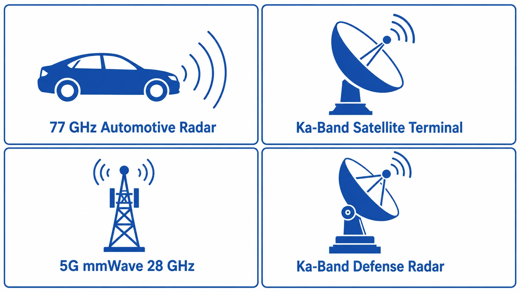
- 77 GHz automotive radar PCB— FMCW front-end and antenna array
- Ka-band satellite terminal PCB— LEO user terminal phased array (Starlink, OneWeb)
- 5G mmWave PCB— 28 GHz base station massive MIMO antenna
- Phased array PCB— Ka-band AESA radar, 5G mmWave beam steering
- Defense Ka-band radar — fire control, missile seeker, airborne radar
- Industrial level measurement radar — 76–77 GHz process control
Conclusion
Rogers RO3003 (Dk 3.0, Df 0.0010) is the standard PTFE ceramic substrate for Ka-band (26.5–40 GHz) and 77 GHz applications. It requires in-house plasma activation, PTFE-specific drill parameters, and a maximum of 2 lamination press cycles — processes not required for RO4350B. Riching PCB stocks RO3003 in 0.127 mm and 0.254 mm dielectric thickness with in-house plasma activation, 7–10 working day prototype lead time, no MOQ. See Rogers materials overview for full thickness availability, or high frequency PCB capabilities for full factory specifications.
Order Rogers RO3003 PCB — In-House Plasma Activation
RO3003 in 0.127 mm and 0.254 mm in stock. 7–10 day prototype. Send the following:
- Gerber files + NC drill file
- RO3003 dielectric thickness (0.127 mm or 0.254 mm)
- Copper weight per layer
- Controlled impedance target and tolerance
- Operating frequency and application type
- IPC Class and quantity
WhatsApp +86 13760473650 — DFM review within 24 hours
Rogers RO3003 PCB Q&A
Common questions about Rogers RO3003 applications, differences from RO4350B and RT5880, available thicknesses and plasma activation requirements.
What is Rogers RO3003 used for?
Standard substrate for Ka-band PCB (26.5–40 GHz), 77 GHz automotive radar, 5G mmWave 28 GHz base station antenna, Ka-band phased arrays, and LEO satellite terminals (Starlink, OneWeb Ka-band CPE).
What is the difference between RO3003 and RO4350B?
RO3003 is PTFE ceramic (Df 0.0010), plasma activation required, 7–10 day lead time. RO4350B is hydrocarbon ceramic (Df 0.0037), FR4-compatible process, 5–7 day lead time. At 30 GHz: RO3003 ~0.5 dB/cm vs RO4350B ~1.8 dB/cm insertion loss. RO4350B for below 12 GHz; RO3003 required above 20 GHz.
What is the difference between RO3003 and RT5880?
Both PTFE-based, both suitable for Ka-band and 77 GHz. RT5880 Df 0.0009 (10% lower) but Dk 2.20 vs 3.0 means ~17% larger antenna elements and much lower thermal conductivity (0.20 vs 0.50 W/m/K). RO3003 preferred for most radar and Ka-band designs. RT5880 for minimum insertion loss or wideband 2–40 GHz.
What thicknesses are available for Rogers RO3003?
0.127 / 0.254 / 0.508 / 0.762 / 1.524 mm. For Ka-band and 77 GHz: 0.127 mm standard. 50Ω microstrip on 0.127 mm with 0.5 oz copper: ~0.28 mm — enables dense patch arrays with ~5 mm element spacing at 28 GHz.
Does Rogers RO3003 require plasma activation?
Yes — PTFE ceramic, in-house plasma activation mandatory before copper plating. Without it, copper adhesion fails under thermal cycling. Max 2 lamination press cycles. Riching PCB performs in-house plasma on all RO3003 orders. 7–10 day prototype, no MOQ.
Request a PCB Quote
Upload your Gerber ZIP file and project requirements. Our engineering team will review your PCB material, stackup, impedance needs, surface finish, and production quantity before quoting.
Please prepare:
- Gerber files in ZIP format
- PCB material or stackup requirements
- Controlled impedance notes if available
- Prototype or batch production quantity
