PTFE PCB Drilling: Parameters, Smear Problems and How to Drill Rogers PTFE Correctly

Why PTFE requires reduced spindle speed, what PTFE smear is and why it blocks plasma activation, correct drill parameters for RO3003 and RT5880, and entry/backup material requirements.

Table of Contents

Key point: Most factories use FR4 spindle speed (80,000–120,000 RPM) on PTFE — this melts PTFE on the hole wall, creating smear that blocks plasma activation even if plasma is performed correctly. Correct PTFE drilling requires 40,000–60,000 RPM spindle speed, reduced feed and retract rates, aluminum entry material, and phenolic backup board.

Most factories quote 3–4 weeks waiting for RO3003 / RT5880 material procurement. Riching PCB maintains these materials in stock with PTFE-specific drill programs — no material wait, 7–10 working day prototype.

Drilling is the first critical step in PTFE PCB manufacturing — and the step most commonly done wrong at factories without genuine PTFE process capability. PTFE is a soft, viscoelastic material. At the spindle speeds used for FR4 (80,000–120,000 RPM), PTFE heats up and melts around the drill bit, depositing a smooth PTFE film on the hole wall. This smear layer is chemically identical to the bulk PTFE substrate — it is just as inert and just as resistant to copper adhesion. Even perfect plasma activation cannot penetrate through PTFE smear to activate the surface underneath.

This guide covers PTFE drilling parameters, what smear looks like and why it matters, entry and backup material requirements, and how to verify your factory uses correct PTFE drill programs.

Why FR4 Drill Parameters Fail on PTFE

The fundamental problem is heat. FR4 is a rigid thermoset material — it does not soften significantly at drill temperatures. PTFE is a thermoplastic with a low melting point of approximately 327°C. At FR4 spindle speeds, friction between the drill bit and the PTFE hole wall generates enough heat to partially melt the PTFE surface. The softened PTFE smears along the hole wall as a smooth, continuous film.

This smear layer has three consequences:

  • It covers the PTFE surface roughness needed for plasma activation to work
  • It creates a chemically uniform PTFE surface — smooth and inert — that electroless copper cannot nucleate on
  • It can be partially removed by desmear, but heavy smear requires aggressive desmear that risks damaging the copper of inner layers in multilayer boards

Correct PTFE Drill Parameters

ParameterFR4 TypicalPTFE (RO3003/RT5880)Consequence of FR4 Params on PTFE
Spindle speed80,000–120,000 RPM40,000–60,000 RPMPTFE melts and smears — blocks plasma activation
Feed rateStandard per drill sizeReduced 20–30%Fast feed tears PTFE, creates rough hole wall
Retract rateStandardReducedFast retract pulls PTFE debris back into hole
Entry materialStandard aluminumAluminum or phenolicPrevents PTFE smear at board entry
Backup materialStandard phenolicPhenolic requiredPrevents PTFE smear at board exit
Hit count per bitStandardReduced 30–50%Worn bits smear more — replace more frequently

The key parameter is spindle speed reduction — typically to 40,000–60,000 RPM for PTFE vs 80,000–120,000 RPM for FR4. Lower spindle speed reduces friction heat, keeping the PTFE below its softening temperature during drilling. Feed rate and retract rate are also reduced to prevent tearing of the soft PTFE and to avoid pulling debris back into the drilled hole.

What PTFE Smear Looks LikePTFE smear comparison showing smeared hole wall from FR4 drill speed versus clean hole wall from correct PTFE parameters

Smear SymptomCauseConsequence
PTFE film on hole wallExcessive spindle speed melts PTFEBlocks plasma activation — copper won't adhere
Rough or torn hole wallFast feed rate on soft PTFEPoor copper plating uniformity
PTFE debris in holeInadequate desmearBlocks electroless copper nucleation
Undersized hole diameterPTFE springback after drillVia resistance out of spec
Copper separation after reflowSmear + insufficient plasmaField failure — board must be scrapped

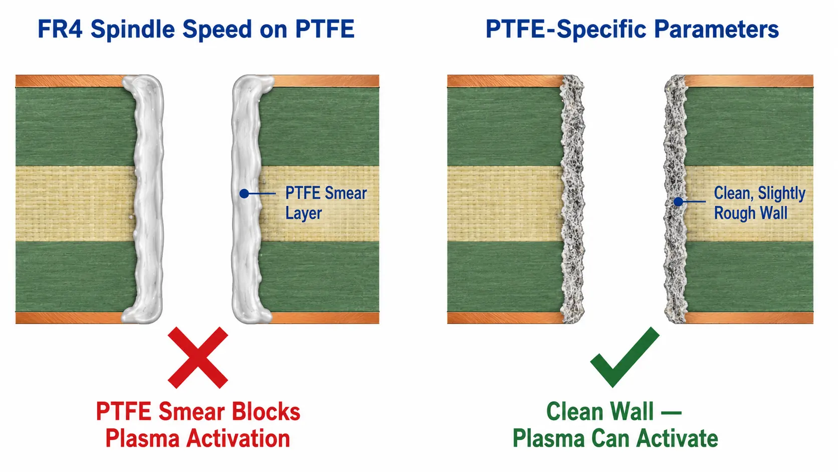
PTFE smear is not always visible under routine optical inspection. The hole may appear clean at low magnification. Under SEM (scanning electron microscopy) or cross-section analysis, smear appears as a smooth, continuous PTFE film covering the micro-roughness of the hole wall. A properly drilled PTFE hole wall has visible micro-texture from the drill cut — this texture is what plasma activation enhances to allow copper adhesion.

Entry and Backup Material RequirementsPTFE PCB drilling stack setup showing entry material and backup board arrangement for Rogers substrate drilling

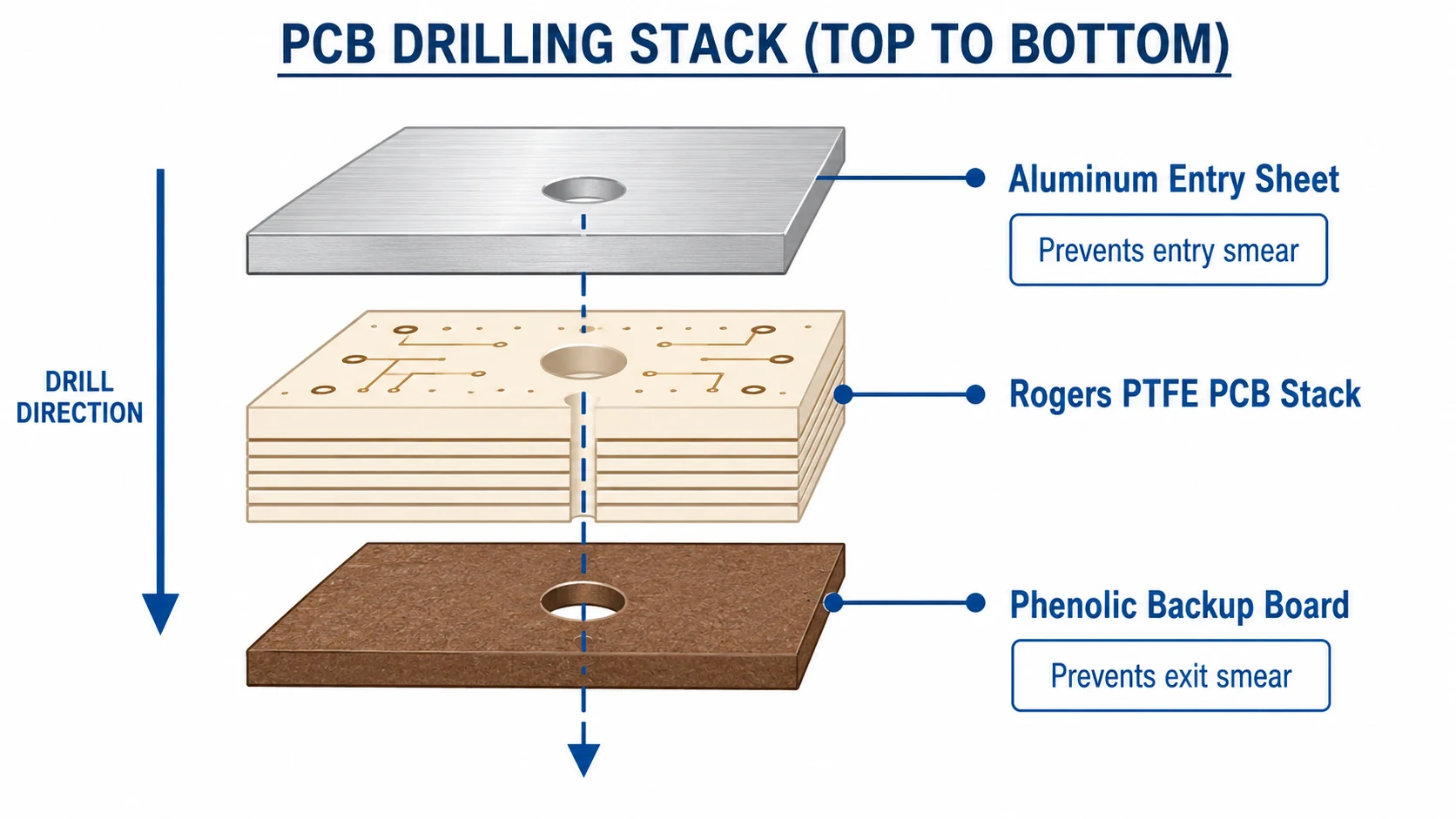
Entry Material (Top of Stack)

Entry material is placed on top of the PCB stack before drilling. For PTFE, aluminum sheet is standard — it conducts heat away from the drill entry point, reducing the thermal spike as the bit enters the soft PTFE surface. The aluminum also provides a clean, rigid entry surface that prevents the drill from wandering at entry.

Backup Material (Bottom of Stack)

Backup material is placed under the PCB stack. For PTFE, phenolic (hard paper-based) backup board is required. At exit, the drill pulls PTFE material downward — without a firm backup board, this exit force creates PTFE smear at the bottom of the hole. Phenolic provides the correct support stiffness to prevent exit smear without damaging the drill bit.

Stack Height

PTFE drilling typically processes fewer boards per stack than FR4 — often 1–2 boards per stack vs 3–5 for FR4. More boards per stack increases heat accumulation and smear risk. Reduced stack height is part of correct PTFE drill process setup.

Bit Life and Replacement

PTFE is abrasive and adheres to carbide drill bits. A worn drill bit with reduced cutting edge geometry smears more than a sharp bit. For PTFE, hit count per bit is reduced 30–50% compared to FR4. Using FR4 hit count limits on PTFE leads to increasing smear as the bit wears — the last holes drilled with a worn bit have significantly worse hole wall quality than the first.

How to Verify Your Factory Uses Correct PTFE Drill Parameters

  • Ask directly: do you have separate drill programs for PTFE materials, or do you use the same parameters as FR4?
  • Ask for the spindle speed used for RO3003 — a factory with PTFE capability quotes 40,000–60,000 RPM
  • Ask whether PTFE is drilled in separate stacks from FR4 boards — it should be
  • Request cross-section analysis photos from a previous PTFE order — clean hole wall with visible micro-texture confirms correct drilling

A factory that uses FR4 drill parameters on PTFE will not volunteer this information. The lead time test remains the fastest check: RO3003 prototype in 7–10 days indicates a factory with genuine PTFE process knowledge. FR4-equivalent lead time indicates a factory applying FR4 process to PTFE materials.

Which PTFE Materials Require Special Drilling

All PTFE-based materials require reduced spindle speed and PTFE-specific drill parameters:

  • Rogers RO3003(Dk 3.0, PTFE ceramic)
  • Rogers RT5880(Dk 2.20, PTFE glass) — softest, most prone to smear
  • Rogers RT5870, RO3006, RO3010, RO6010
  • Taconic TLY-5, TLP-5, RF-35, CER-10
  • F4BM220, F4BTM series

Rogers RO4350B and RO4003C are hydrocarbon ceramic — not PTFE — and use standard FR4 drill parameters. See PTFE PCB plasma activation guide for the next process step after drilling.

Conclusion

PTFE PCB drilling requires reduced spindle speed (40,000–60,000 RPM), PTFE-specific feed and retract rates, aluminum entry material, phenolic backup board, and reduced bit hit counts. Using FR4 drill parameters on PTFE creates hole wall smear that blocks plasma activation and prevents copper adhesion — producing boards that pass initial testing and fail in the field. Riching PCB uses PTFE-specific drill programs for all RO3003, RT5880, Taconic and F4B orders. RO3003 and RT5880 in stock — no material procurement wait, 7–10 working day prototype. See PTFE PCB manufacturing overview for the complete process guide.

Order PTFE PCB with Correct Drilling Process

RO3003, RT5880, Taconic in stock. PTFE-specific drill programs. In-house plasma activation. 7–10 day prototype.

  • Gerber files + NC drill file
  • PTFE material grade and dielectric thickness
  • Stackup drawing — copper weight per layer
  • Controlled impedance requirements
  • IPC Class and quantity

WhatsApp +86 13760473650— DFM review within 24 hours

Q&A

PTFE PCB Drilling Q&A

Common questions about PTFE drill parameters, smear causes, entry/backup materials, and how to verify factory capability.

Why does PTFE require different drill parameters than FR4?

PTFE melting point ~327°C. FR4 spindle speed (80–120K RPM) heats hole wall above softening temperature — PTFE melts and smears. Smear blocks plasma activation. Correct: 40–60K RPM keeps PTFE below softening temperature during drilling.

What is PTFE smear and why does it matter?

Melted PTFE coating the hole wall from excessive drill speed. Chemically identical to bulk PTFE — smooth, inert, prevents copper adhesion. Plasma activation cannot penetrate through smear. Boards fail after 3–5 thermal cycles.

What entry and backup materials are required for PTFE drilling?

Entry (top): aluminum sheet — conducts heat, prevents entry smear. Backup (bottom): phenolic board — firm support, prevents exit smear. Stack height: 1–2 boards per stack (vs 3–5 for FR4) to minimize heat accumulation.

How do I verify a factory uses correct PTFE drill parameters?

Ask spindle speed for RO3003 — correct: 40–60K RPM. Ask if PTFE boards drilled separately from FR4. Ask about PTFE bit hit count limits. Lead time test: RO3003 in 7–10 days = genuine PTFE knowledge.

Does Rogers RO4350B require PTFE drill parameters?

No — RO4350B and RO4003C are hydrocarbon ceramic, not PTFE. Standard FR4 drill parameters apply. Only PTFE-based materials (RO3003, RT5880, Taconic, F4B) need reduced spindle speed and plasma activation.

PCB Project Review

Request a PCB Quote

Upload your Gerber ZIP file and project requirements. Our engineering team will review your PCB material, stackup, impedance needs, surface finish, and production quantity before quoting.

Please prepare:

  • Gerber files in ZIP format
  • PCB material or stackup requirements
  • Controlled impedance notes if available
  • Prototype or batch production quantity
ZIP format only. Please compress all Gerber and drill files into one ZIP package before uploading.