F4B PCB as Rogers Alternative: Grade Guide, Dk/Df Comparison and When to Switch
Complete guide to F4B PTFE PCB materials as Rogers alternatives — F4BM220 vs RT5880, F4BM300 vs RO3003, full grade Dk/Df data, 25–35% cost saving, and when F4B works vs when Rogers is required.
Table of Contents
Key point: F4BM220 (Dk 2.20, Df 0.0010) is a practical RT5880 alternative at 25–35% lower cost — same Dk, Df only 11% higher. F4BM300 (Dk 3.0, Df 0.0017) vs RO3003 (Df 0.0010) — 70% higher Df, adds ~3.5 dB insertion loss over 10 cm at 28 GHz. All F4B materials require the same in-house plasma activation as Rogers PTFE.
Riching PCB stocks F4BM220 and other F4B grades with in-house plasma activation. 7–10 day prototype, no MOQ. No material procurement wait.
F4B is a range of PTFE-based RF PCB substrates manufactured by Wangling Electronics (泰兴旺灵) in China. The F4B series covers Dk values from 2.20 to 6.15, spanning the same range as Rogers PTFE materials from RT5880 to RO3006. At equivalent Dk and Df values, F4B materials cost 25–35% less than comparable Rogers grades.
F4B requires the same manufacturing process as Rogers PTFE — in-house plasma activation before copper plating, PTFE-specific drill parameters, maximum 2 lamination press cycles. The process cost is identical to Rogers; the saving is in material cost only.
This guide covers all major F4B grades, direct Rogers equivalents, the practical Df differences that matter at different frequencies, and when F4B is a suitable substitution vs when Rogers material traceability or tighter Dk tolerance is required.
F4B Grade Overview
| F4B Grade | Dk | Df | Rogers Equivalent | Notes |
|---|---|---|---|---|
| F4BM220 | 2.20±0.04 | 0.0010 | RT5880 (Dk 2.20, Df 0.0009) | Very close — Df only 11% higher |
| F4BM255 | 2.55±0.05 | 0.0013 | RT5870 approx. | Mid-range Dk |
| F4BM300 | 3.0±0.05 | 0.0017 | RO3003 (Dk 3.0, Df 0.0010) | 70% higher Df than RO3003 |
| F4B350 | 3.5±0.05 | 0.0025 | RO4350B approx. / RF-35 | PTFE process — unlike RO4350B |
| F4BTM400 | 4.0±0.08 | 0.0030 | No direct Rogers equivalent | High Dk compact designs |
| F4BTM440 | 4.4±0.10 | 0.0033 | No direct Rogers equivalent | Higher Dk compact designs |
| F4BTM615 | 6.15±0.12 | 0.0045 | RO3006 (Dk 6.15, Df 0.0020) | Higher Df than RO3006 |

F4BM220 vs Rogers RT5880: The Closest Match
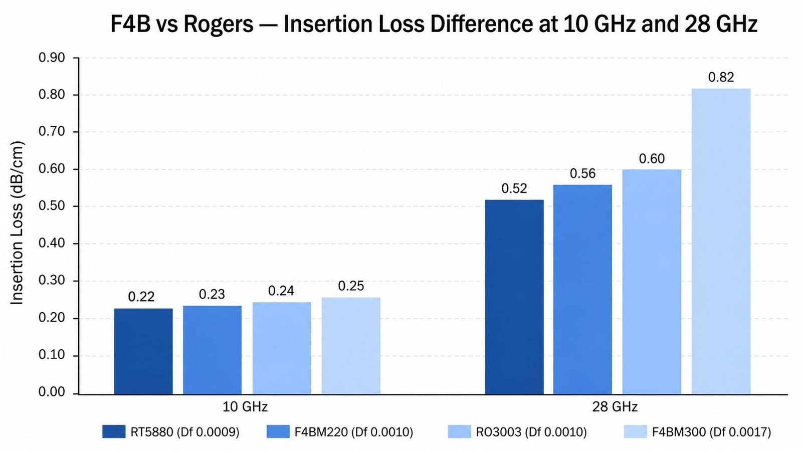
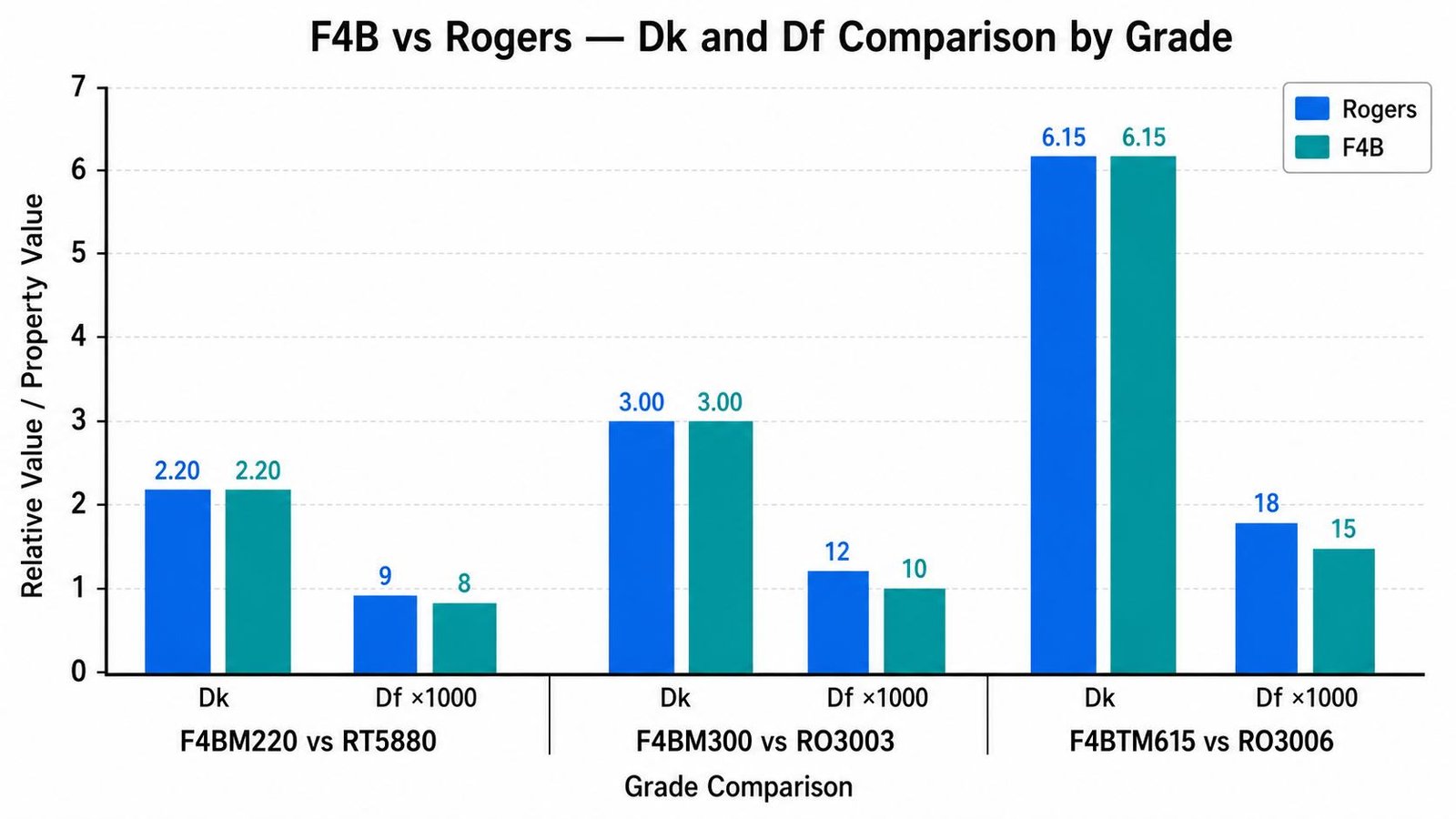
F4BM220 (Dk 2.20 ±0.04, Df 0.0010) is the closest F4B equivalent to Rogers RT5880 (Dk 2.20, Df 0.0009). The Dk values are identical. The Df difference is 0.0001 — 11% higher for F4BM220. At 10 GHz, this produces approximately 0.02 dB/cm additional insertion loss — negligible for most designs. At 28 GHz, the difference is approximately 0.07 dB/cm — still small for most applications.
F4BM220 is a practical substitute for RT5880 in most commercial EW (2–18 GHz) and Ka-band designs where the extra 0.0001 Df is within the RF performance budget. The material cost saving vs Rogers RT5880 is approximately 25–35%. Available thicknesses: 0.127 / 0.254 / 0.508 / 0.762 / 1.016 / 1.524 mm.
F4BM300 vs Rogers RO3003: Higher Df Gap
F4BM300 (Dk 3.0 ±0.05, Df 0.0017) vs Rogers RO3003 (Dk 3.0, Df 0.0010). The Dk values match. The Df difference is 0.0007 — 70% higher for F4BM300. At 10 GHz, this represents approximately 0.10 dB/cm additional insertion loss. At 28 GHz (Ka-band): approximately 0.35 dB/cm additional loss — over a 10 cm feed network, this is 3.5 dB more insertion loss than RO3003.
For designs where the link budget has 3.5 dB of margin, F4BM300 is a viable substitute for RO3003 at Ka-band. For tight Ka-band designs — 77 GHz automotive radar, Ka-band phased arrays with precise beam performance — the Df gap is significant and RO3003 is required.
Dk Uniformity: The Key Difference for Phased Arrays
Rogers material Dk tolerance: RO3003 Dk 3.0 ±0.04; RT5880 Dk 2.20 ±0.02. These are tight specifications maintained across every production lot with documented lot-level Dk data.
F4B Dk tolerance: F4BM220 Dk 2.20 ±0.04; F4BM300 Dk 3.0 ±0.05. The nominal tolerance is similar to Rogers, but production consistency across panels varies more than Rogers premium PTFE. For single or double layer RF PCB where the entire board uses one core, this is generally acceptable. For phased array PCB where Dk uniformity across the panel is critical — because Dk variation causes phase errors between antenna elements — Rogers materials provide more predictable panel-level performance.
See phased array PCB guide for the Dk uniformity requirements for phased array applications.
When F4B Works and When Rogers Is Required
| Scenario | F4B Suitable? | Reason |
|---|---|---|
| General RF PCB 1–12 GHz | ✅ Yes | Df difference small at lower frequencies |
| EW receiver 2–18 GHz | ✅ Yes with Df check | F4BM220 Df 0.0010 acceptable for most EW |
| Ka-band 28 GHz standard design | ⚠️ Check Dk uniformity | F4BM300 Df 0.0017 — 70% higher than RO3003 |
| Phased array — Dk uniformity critical | ⚠️ Verify lot data | Rogers specifies tighter Dk tolerance |
| 77 GHz automotive radar | ❌ Not recommended | At 77 GHz, Df gap is significant |
| Military spec / IPC Class 3 | ⚠️ Confirm with customer | Rogers material traceability may be required |
| Cost-sensitive commercial RF | ✅ Good choice | 25–35% material saving for equivalent application |
Manufacturing: Same Process as Rogers PTFE
F4B is PTFE-based — all manufacturing requirements identical to Rogers PTFE:
- In-house plasma activation required — same 2-hour window before copper plating
- PTFE-specific drill parameters — reduced spindle speed
- Maximum 2 lamination press cycles
- ENIG surface finish standard
- Lead time at Riching PCB: 7–10 working days — same as Rogers PTFE
Available Thicknesses at Riching PCB
F4BM220: 0.127 / 0.254 / 0.508 / 0.762 / 1.016 / 1.524 mm — in stock
F4BM255, F4BM265, F4BM300, F4B350, F4BTM400, F4BTM440, F4BTM615: available, confirm current stock on enquiry
Conclusion
F4BM220 (Dk 2.20, Df 0.0010) is a practical Rogers RT5880 alternative at 25–35% lower material cost for EW and standard Ka-band applications. F4BM300 (Dk 3.0, Df 0.0017) is a viable RO3003 substitute for designs with sufficient insertion loss margin, but its 70% higher Df makes it unsuitable for 77 GHz radar, tight Ka-band phased arrays, or designs with minimal link budget. All F4B PTFE materials require the same in-house plasma activation as Rogers PTFE. Riching PCB stocks F4BM220 and other F4B grades with in-house plasma activation — same 7–10 day prototype lead time as Rogers PTFE, no MOQ. See Rogers PCB cost reduction guide for the full cost optimization strategy.
Order F4B or Rogers PCB — In Stock, In-House Plasma
F4BM220, Rogers RO3003, RT5880 all in stock. Same 7–10 day prototype lead time. No MOQ.
- Gerber files + NC drill file
- Material grade (F4B or Rogers) and dielectric thickness
- Copper weight per layer
- Controlled impedance requirements
- IPC Class and quantity
WhatsApp +86 13760473650— quotation within 24 hours
F4B PCB Rogers Alternative Q&A
Common questions about F4BM220 vs RT5880, F4BM300 vs RO3003, plasma activation requirements and when Rogers is required.
Is F4BM220 a direct replacement for Rogers RT5880?
Very close — same Dk 2.20, Df only 11% higher (0.0010 vs 0.0009). Adds ~0.02 dB/cm at 10 GHz. For EW and standard Ka-band within link budget margin: practical substitute at 25–35% lower cost.
Can F4BM300 replace Rogers RO3003?
Same Dk 3.0, but Df 70% higher (0.0017 vs 0.0010). At 28 GHz: ~0.35 dB/cm more loss, 3.5 dB over 10 cm. OK for designs with sufficient budget margin. Not for 77 GHz radar, tight phased arrays, or minimal link budget.
Does F4B PCB require plasma activation?
Yes — PTFE-based, same requirements as Rogers RO3003 and RT5880. In-house plasma, 2-hour window to plating, max 2 lamination cycles, PTFE drill parameters. Riching PCB performs in-house plasma on all F4B orders.
What is the cost saving of F4B vs Rogers?
F4BM220 vs RT5880: ~25–35% lower material cost. F4BM300 vs RO3003: ~20–30% lower. Process cost identical. Total board cost saving is lower than material saving.
When should I use Rogers instead of F4B?
77 GHz radar, tight Ka-band phased arrays needing Dk uniformity, military spec needing Rogers traceability, or when Df gap causes unacceptable insertion loss in your link budget. All other commercial RF: F4B is practical.
Request a PCB Quote
Upload your Gerber ZIP file and project requirements. Our engineering team will review your PCB material, stackup, impedance needs, surface finish, and production quantity before quoting.
Please prepare:
- Gerber files in ZIP format
- PCB material or stackup requirements
- Controlled impedance notes if available
- Prototype or batch production quantity
