
Rigid Flex PCB Manufacturer — 2–50 Layer, ISO13485 & IATF16949
Riching PCB manufactures rigid-flex PCB and FPC flex circuits for medical, defense, automotive and wearable applications. 2–50 layers, polyimide flex with FR4 or Rogers rigid sections. ISO13485 and IATF16949 certified. IPC Class 3 on request. Laser drill 0.1mm. No MOQ, from 1 board.
Home » Rigid Flex PCB Manufacturer — 2–50 Layer, ISO13485 & IATF16949
Table of Contents
2–50
layers
rigid-flex & FPC
0.1mm
laser drill
fine-pitch flex
ISO13485
& IATF16949
certified
No MOQ
From 1 board
IPC Class 2 / 3
Rigid-Flex vs FPC — Which to Choose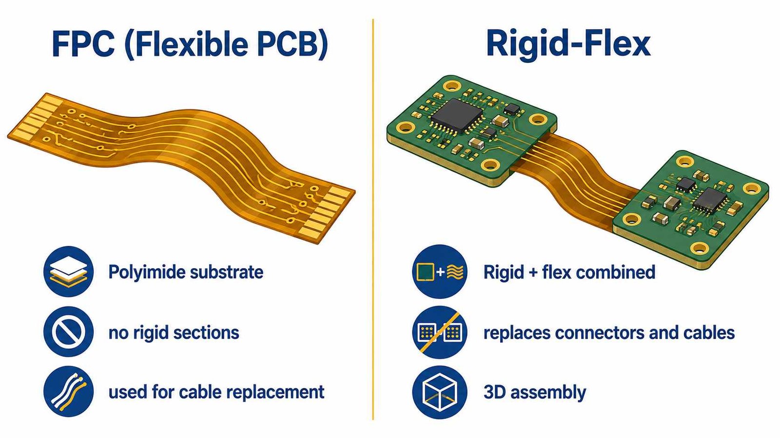
FPC (Flexible PCB) is a pure flexible circuit — polyimide substrate, no rigid sections, typically used as a cable replacement between two rigid PCBs. Rigid-flex combines rigid and flexible sections in a single board, replacing both the PCBs and the connector/cable between them. Rigid-flex reduces assembly steps, improves reliability in high-vibration environments and enables 3D packaging in tight spaces.
Both are manufactured in-house at Riching PCB — confirm in DFM review which approach fits your design constraints and assembly process.
Manufacturing Capability
| Parameter | Flex / FPC | Rigid-Flex |
|---|---|---|
| Layer count | 1–12 layers | 2–50 layers (rigid sections up to 50L) |
| Min trace/space | 3mil/3mil standard | 3mil/3mil standard, 2.5mil/2.5mil advanced |
| Min drill | 0.1mm laser | 0.1mm laser / 0.2mm mechanical |
| Flex material | Polyimide (PI) standard | PI flex layers bonded to FR4 or Rogers rigid sections |
| Coverlay | Polyimide coverlay standard | PI coverlay on flex sections, soldermask on rigid |
| Surface finish | ENIG standard | ENIG / ENEPIG / hard gold |
| Bend radius | Min 6× flex thickness | Design review required — confirm before DFM |
| IPC Class | Class 2 standard | Class 3 on request (ISO13485 / IATF16949) |
Applications
| Application | Board Type | Key Requirement |
|---|---|---|
| Wearable medical sensor | FPC / rigid-flex | Thin, flexible, biocompatible ENIG |
| Ultrasound probe array | Rigid-flex | Fine pitch, flex bend at probe neck |
| Endoscope camera module | FPC + rigid-flex | Ultra-thin, 0.1mm laser drill |
| Implantable device | Rigid-flex | IPC Class 3, ISO13485, ENEPIG |
| Drone / UAV flight controller | Rigid-flex | Space saving, vibration resistant |
| Automotive radar module | Rigid-flex + Rogers | RO3003 rigid section + PI flex interconnect |
| Consumer wearable | FPC | Low cost, high volume, thin |
Certifications for Medical and Automotive Rigid-Flex
- ISO13485 — medical device quality management, see medical PCB manufacturer
- IATF16949 — automotive quality management, see automotive PCB manufacturer
- ISO9001 — general quality management baseline
- IPC Class 3 — on request, for life-sustaining and safety-critical applications
- Full material traceability — lot records for medical and defense programs
Rogers + Rigid-Flex for RF Applications
For RF and microwave designs requiring flex interconnects between RF modules — such as 77GHz radar or Ka-band phased array assemblies — rigid-flex stackups with Rogers rigid sections and polyimide flex sections are available. Rogers 4450F bondply used at the rigid-to-flex transition zones. Confirm stackup in DFM review.
How to Order
- WhatsApp: +86 13760473650
- Send: Gerber zip + NC drill + stackup/layer drawing (mark rigid and flex zones clearly)
- Specify: IPC Class, bend radius, coverlay/stiffener requirements, certification needs
- DFM review: 4–8 hours — includes bend zone verification and layer transition check
- No MOQ. From 1 board.
Frequently Asked Questions — Rigid Flex PCB Design
What is the minimum bend radius for rigid-flex PCB?
Can soldermask be used on rigid-flex PCB flex sections?
Can vias be placed in the flex zone?
How should traces be routed in the flex zone?
Rigid Flex PCB Manufacturer — Shenzhen, ISO13485 & IATF16949
2–50 Layer Rigid-Flex & FPC
Medical · Defense · Automotive · No MOQ
Send Gerber + layer drawing (mark rigid and flex zones).
DFM review within 4–8 hours including bend zone check.
DFM review within 4–8 hours
Request a PCB Quote
Upload your Gerber ZIP file and project requirements. Our engineering team will review your PCB material, stackup, impedance needs, surface finish, and production quantity before quoting.
Please prepare:
- Gerber files in ZIP format
- PCB material or stackup requirements
- Controlled impedance notes if available
- Prototype or batch production quantity