77GHz Radar PCB Manufacturer — RO3003 0.127mm In Stock
Riching PCB manufactures 77GHz FMCW radar PCB on Rogers RO3003 0.127mm — the standard substrate for 76–81GHz automotive radar, industrial level measurement radar and defense Ka-band applications. RO3003 0.127mm in stock. In-house plasma activation. 7–10 day prototype. No MOQ.
Home » 77GHz antenna array PCB » 77GHz Radar PCB Manufacturer — RO3003 0.127mm In Stock
Table of Contents
In stock
RO3003 0.127mm
No procurement delay
7–10
day prototype
from DFM approval
±5%
TDR impedance
available on request
No MOQ
From 1 board
IPC Class 2 / 3
Why 77GHz Radar Requires RO3003 0.127mm
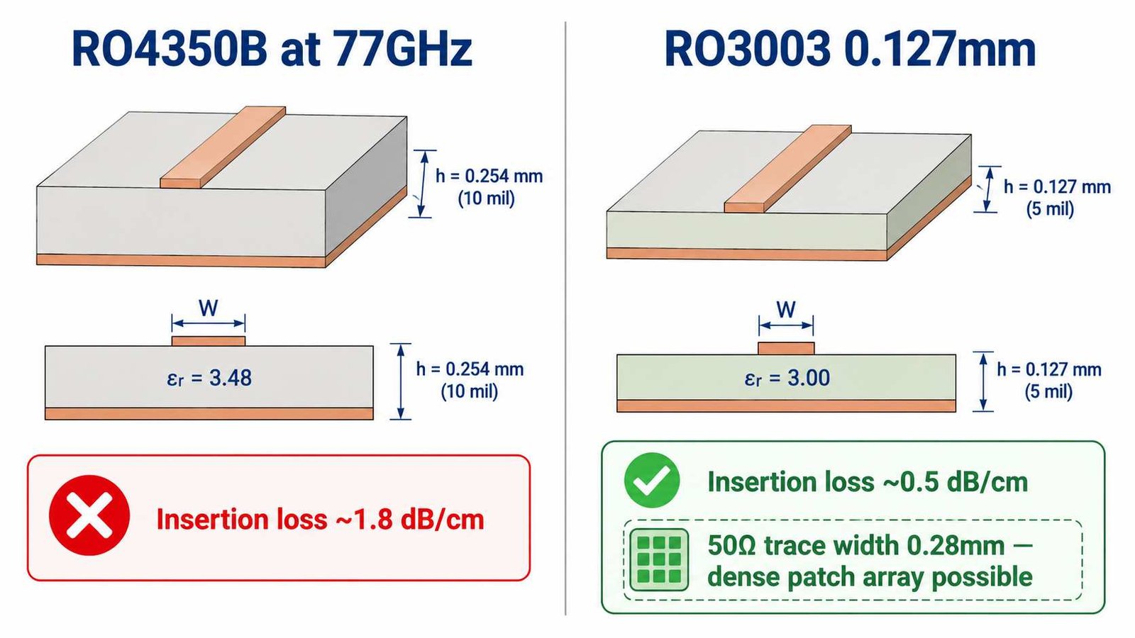
At 77GHz, insertion loss is the primary design constraint. Rogers RO4350B (Df 0.0037) produces approximately 1.8 dB/cm — over a 10cm feed network, 18dB of loss. Rogers RO3003 (Df 0.0010, PTFE ceramic) produces approximately 0.5 dB/cm — 5dB over the same network. This is why 77GHz radar PCB requires PTFE substrate, not hydrocarbon ceramic.
The 0.127mm dielectric thickness is standard for 77GHz for two reasons: the thin substrate produces a 50Ω microstrip trace width of ~0.28mm with 0.5oz copper, enabling λ/2 patch element spacing of ~1.95mm at 77GHz. And the thin substrate keeps the board weight minimal — critical for automotive radar modules.
Manufacturing Specifications
| Parameter | Specification | Notes |
|---|---|---|
| Primary substrate | Rogers RO3003 0.127mm | Standard for 77GHz FMCW front-end and antenna array |
| Copper weight | 0.5 oz (outer layer) | Finer trace resolution for λ/2 patch spacing ~1.95mm |
| 50Ω microstrip width | ~0.28mm | 0.127mm core, 0.5oz copper — confirm with Dk certificate |
| Via fence pitch (77GHz) | ≤0.6mm center-to-center | λ/10 in RO3003 at 77GHz |
| Min drill diameter | 0.2mm mechanical | Laser drill 0.1mm available for tighter via fence |
| Impedance tolerance | ±10% standard / ±5% available | ±5% requires TDR report — specify on drawing |
| Surface finish | ENIG | Flat surface critical for patch dimensional accuracy |
| IPC Class | Class 2 standard / Class 3 on request | Class 3 for automotive safety-critical programs |
| Prototype lead time | 7–10 working days | RO3003 in stock — no material procurement delay |
Module Types Supported
| Module Type | Substrate | Key Design Consideration |
|---|---|---|
| FMCW front-end (TX/RX) | RO3003 0.127mm | Tight impedance — ±5% TDR recommended |
| Patch antenna array (76–77GHz) | RO3003 0.127mm | λ/2 spacing ~1.95mm, ENIG for dimensional accuracy |
| Corporate feed network | RO3003 0.127 / 0.254mm | Via fence λ/10 ≤0.6mm pitch required |
| Beamforming IC interface | RO3003 0.127mm | BGA pad design — min drill 0.2mm |
| Hybrid analog/digital | RO3003 + FR4 inner layers | Rogers 2929 bondply at PTFE/FR4 interface |
| High isolation channel separation | Stripline inner RO3003 | 2× ground planes — reduces cross-coupling |
Critical Process Requirements for 77GHz
- RO3003 0.127mm in stock — no 3–4 week procurement delay
- In-house plasma activation — copper adhesion verified, not outsourced
- PTFE-specific drill parameters — 40–60K RPM, prevents hole wall smear
- ENIG surface finish — flat surface critical for patch antenna dimensional accuracy
- Via fence: 0.2mm min drill, 0.4mm center-to-center — achievable at Riching PCB for λ/10 spacing at 77GHz
- TDR ±5% available — specify on stackup drawing
- DFM review includes: 50Ω trace width vs production Dk, via fence spacing vs operating frequency, BGA pad annular ring check
Lead Time
- Prototype (1–10 boards): 7–10 working days from DFM approval
- Small production (10–50 boards): 10–14 working days
- DHL Express to USA / Europe / Israel: 3–5 working days after shipment
- Total door-to-door prototype: 10–15 working days
How to Order
- WhatsApp: +86 13760473650
- Send: Gerber zip + NC drill + stackup drawing
- Specify: RO3003 0.127mm, copper weight (0.5oz or 1oz), impedance target, IPC Class
- DFM review: 4–8 hours
77GHz Radar PCB Manufacturer — Shenzhen Direct Factory
RO3003 0.127mm In Stock
7–10 Day Prototype · No MOQ · In-House Plasma
Send Gerber + stackup drawing. DFM review within 4–8 hours.
Specify RO3003 0.127mm, 0.5oz copper, impedance target.
DFM review within 4–8 hours
Request a PCB Quote
Upload your Gerber ZIP file and project requirements. Our engineering team will review your PCB material, stackup, impedance needs, surface finish, and production quantity before quoting.
Please prepare:
- Gerber files in ZIP format
- PCB material or stackup requirements
- Controlled impedance notes if available
- Prototype or batch production quantity
