Ka-Band PCB Manufacturer — RO3003, RT5880 In Stock
Riching PCB manufactures Ka-band PCB (26.5–40 GHz) for LEO satellite user terminals, phased array radar, 5G mmWave 28 GHz base stations and defense Ka-band applications. Rogers RO3003 and RT5880 in stock — no 3–4 week material procurement delay. In-house plasma activation. TDR every lot. 7–10 day prototype. No MOQ.
Home » Ka-Band PCB » Ka-Band PCB Manufacturer — RO3003, RT5880 In Stock
Table of Contents
In stock
RO3003 0.127 / 0.254mm
RT5880 · RO3006
7–10
day prototype
no material wait
In-house
plasma activation
every PTFE order
No MOQ
From 1 board
IPC Class 2 / 3
Why Ka-Band Requires PTFE — Not RO4350B
Ka-band spans 26.5–40 GHz. Above 20 GHz, Rogers RO4350B (Df 0.0037) produces ~1.8 dB/cm insertion loss — over a 10cm antenna feed network, 18dB total loss. Rogers RO3003 (Df 0.0010, PTFE ceramic) produces ~0.5 dB/cm — 5dB over the same path. This 3.6× difference in insertion loss is the reason Ka-band PCB requires PTFE substrate, not hydrocarbon ceramic.
| Parameter | RO3003 (Ka-band standard) | RO4350B (below 18GHz only) |
|---|---|---|
| Dissipation factor Df | 0.0010 | 0.0037 |
| Insertion loss at 28GHz | ~0.5 dB/cm | ~1.8 dB/cm — 3.6× higher |
| Process type | PTFE — plasma activation required | Hydrocarbon — FR4-compatible |
| Prototype lead time | 7–10 days (in stock) | 5–7 days |
| Use above 20GHz | ✅ Standard choice | ❌ Not suitable |
Ka-Band Applications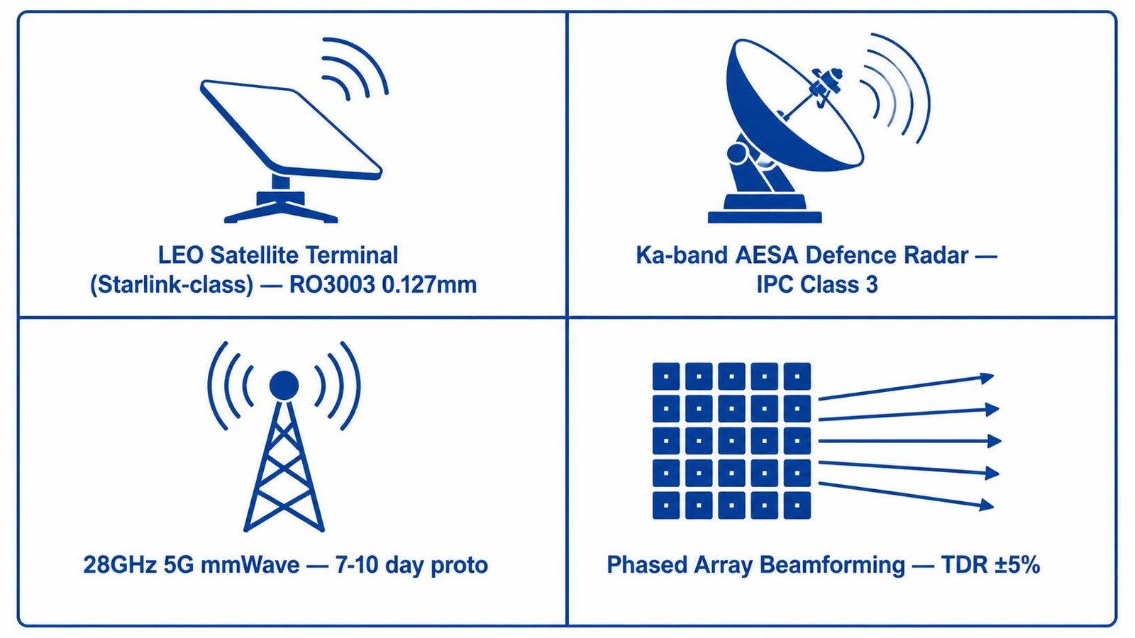
| Application | Material | Riching PCB Advantage |
|---|---|---|
| LEO satellite user terminal | RO3003 0.127 / 0.254mm | Both in stock. Hybrid stackup available. |
| Ka-band AESA defense radar | RO3003 0.127mm | IPC Class 3 on request. ±5% TDR. |
| 28GHz 5G mmWave base station | RO3003 / RT5880 | 7–10 day prototype, no material delay. |
| VSAT terminal uplink/downlink | RO4350B / RO4003C | 5–7 day prototype. FR4-compatible. |
| Phased array beamforming | RO3003 0.127mm | Tight Dk uniformity. TDR ±5% available. |
| Ka-band power amplifier PCB | RO3003 0.254mm | 0.50 W/m/K thermal — better heat spreading. |
| Ka-band filter / diplexer | RO3003 / RO3006 | RO3006 Dk 6.15 in stock — compact designs. |
Material Stock — No Lead Time Penalty
- Rogers RO3003 0.127mm — in stock, standard for Ka-band patch arrays and 28GHz 5G
- Rogers RO3003 0.254mm — in stock, Ka-band feed networks and TX/RX modules
- Rogers RT5880 — in stock 6 thicknesses, lowest loss option for Ka-band minimum insertion loss designs
- Rogers RO3006 Dk 6.15 — in stock, compact Ka-band filter and diplexer designs
- Rogers 4450F and 2929 bondply — in stock, PTFE + FR4 hybrid stackups
Most factories quote 3–4 weeks for RO3003 and RT5880 procurement. Riching PCB maintains these as standard inventory — 7–10 working day prototype from DFM approval.
Process Capabilities for Ka-Band
- In-house RF plasma activation — mandatory for PTFE, performed on-site within 2 hours of plating
- PTFE-specific drill parameters — 40–60K RPM, prevents hole wall smear that blocks plasma
- Max 2 lamination cycles — enforced for all PTFE materials, Dk stability guaranteed
- Min trace/space 2.5mil / 2.5mil — supports fine Ka-band routing
- Min drill 0.2mm mechanical, 0.1mm laser — via fence down to 0.4mm pitch
- TDR ±10% standard, ±5% available — specify on stackup drawing
- ENIG surface finish standard — flat surface for patch element dimensional accuracy
- IPC Class 3 on request — for defense and satellite programs
How to Order
- WhatsApp: +86 13760473650
- Send: Gerber zip + NC drill + stackup drawing (RO3003 grade + dielectric thickness)
- Specify: impedance target (50Ω), tolerance (±10% or ±5%), IPC Class, quantity
- DFM review: 4–8 hours. Quote returned same time.
- No MOQ. From 1 board.
Ka-Band PCB Manufacturer — Shenzhen Direct Factory
RO3003 · RT5880 · RO3006 In Stock
LEO Satellite · Defense Radar · 5G mmWave
Send Gerber + stackup drawing. DFM review within 4–8 hours.
7–10 day prototype. No material procurement delay. IPC Class 2 / 3.
DFM review within 4–8 hours
Related Technical Guides
Rogers RO3003 PCB guide — Ka-band standard material
Request a PCB Quote
Upload your Gerber ZIP file and project requirements. Our engineering team will review your PCB material, stackup, impedance needs, surface finish, and production quantity before quoting.
Please prepare:
- Gerber files in ZIP format
- PCB material or stackup requirements
- Controlled impedance notes if available
- Prototype or batch production quantity