
Antenna OTA and RCS Test Coupon PCB: Designing a Repeatable Reference
OTA and RCS test coupon PCB design: far-field distance, mounting repeatability, diagnostic probe scattering and the thermal drift that moves phase at 77 GHz.
Home » Antenna Measurement » Antenna OTA and RCS Test Coupon PCB: Designing a Repeatable Reference
Table of Contents
A test coupon is not a small product board. It is a reference object: something measured many times, mounted the same way each time, so that a change in the result can be attributed to the design rather than to the setup. Most coupons fail that job not because the board is badly made but because nobody wrote down what the measurement was supposed to be.
That makes coupon design a different discipline from product design. Its specifications are a datum, a distance, a surface and an environment — not a gain target. This page works through the four numbers that decide whether the result means anything. The measurement chain those numbers feed into is covered in our mmWave VNA testing guide.
1. What a Coupon Is Actually For
Three kinds of small high-frequency board get called a coupon in the same meeting, and they answer three different questions.
| Board type | Question it answers | What is specified | What goes wrong |
|---|---|---|---|
| Calibration standard | Is the instrument telling the truth? | Traceable impedance and delay | Drifts with connector wear, not with the design |
| Test coupon | Is this design repeatable, and what is the noise floor? | Geometry, mounting datum, surface, environment | Measured once, never re-measured — so repeatability is unknown |
| Product antenna board | Does the product meet its specification? | Gain, pattern, VSWR over temperature | Interfaces with housing and radome, so it cannot isolate the board |
The coupon is the only one of the three that exists to be measured many times under controlled conditions. Treating it as a small product board is the most common way to waste one.
The distinction matters because the coupon's specification follows from its purpose. A calibration standard is judged on traceability; a product board on performance in its housing; a coupon on the reproducibility of a measurement. A coupon that is optimised for performance and never measured twice is a product board that forgot its housing — and the fixture work that would have made it useful was never done. Fixture structures themselves are the subject of our RF and mmWave test fixture guide.
2. Far-Field Geometry and What It Costs
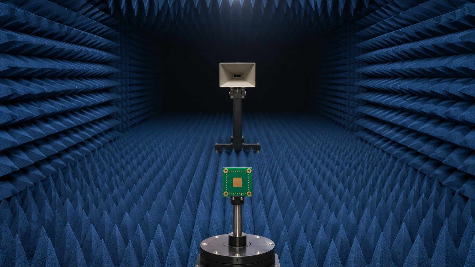
The first number a coupon needs is how far away the probe sits, and the answer is set by the aperture rather than by convenience.
| Quantity | 28 GHz | 77 GHz | 140 GHz |
|---|---|---|---|
| Free-space wavelength | 10.71 mm | 3.893 mm | 2.141 mm |
| Fraunhofer distance, 100 mm aperture | 1.87 m | 5.14 m | 9.34 m |
| Plate RCS, 100 mm square | 10.4 dBsm | 19.2 dBsm | 24.4 dBsm |
| Edge phase taper at 2D²/λ | 22.5° | 22.5° | 22.5° |
The 2D²/λ criterion is not arbitrary: it is the distance at which the phase error across the aperture falls to π/8, which is 0.24 mm of path difference at 77 GHz. Doubling the coupon in size quadruples the distance, which is why large high-frequency coupons are measured in a compact range rather than a direct far-field range.
Two consequences follow. The first is that coupon size is a facility decision as much as an electrical one: a 100 mm coupon at 140 GHz needs 9.3 m, which is beyond most direct far-field ranges and inside a compact range. The second is that the same geometry determines the reflective case, where the coupon's own RCS sets the reference level the measurement is made against. Both sides of that — radiating and scattering — are why antenna assemblies for these bands are specified so tightly, as described in our antenna module PCB assembly page.
3. Mounting Repeatability Is a Phase Specification
Fixtures are drawn in millimetres and judged in millimetres. At 77 GHz the useful unit is degrees, and the conversion is unforgiving.
| Error source | Value at 77 GHz | Consequence |
|---|---|---|
| Mounting repeatability ±0.1 mm | 9.25° single pass | Pattern shift you cannot separate from the design |
| The same tolerance, RCS (two-way) | 18.49° round trip | Reflection budgets are twice as sensitive as transmission budgets |
| Same tolerance at 140 GHz | 16.81° single pass | The fixture has to be twice as good to keep the same budget |
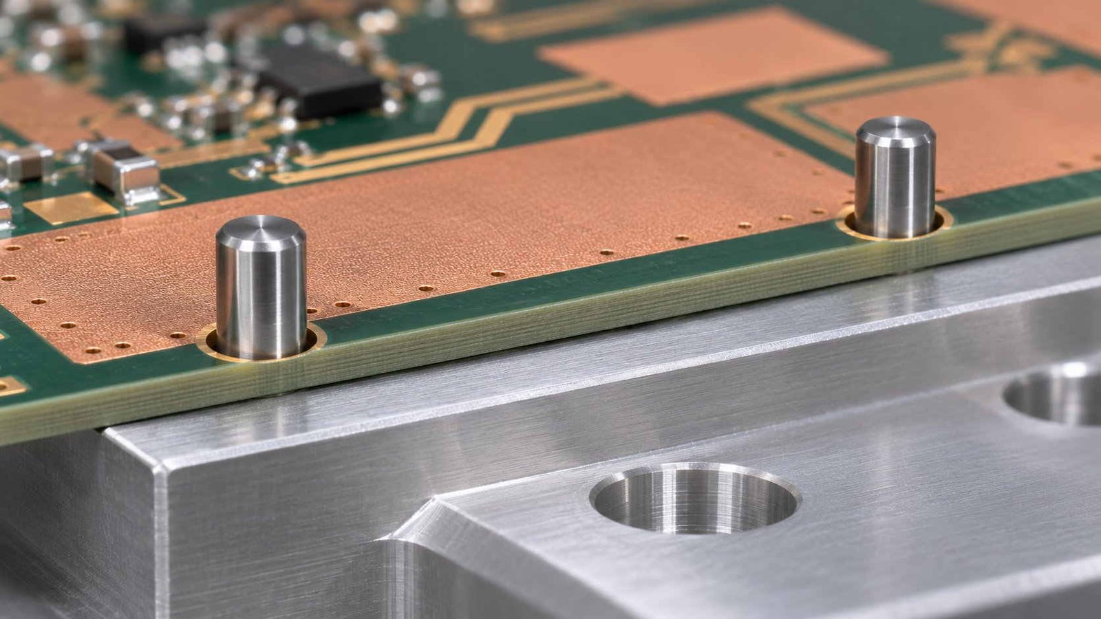
| Datum repeatability with dowel pins | ±0.02–0.05 mm achievable | Costs two holes in the coupon |
A ±0.1 mm fixture sounds precise until it is expressed in degrees. For a reflective measurement the same tolerance costs twice as much phase, which is the single most useful thing to know before specifying a coupon and its holder.
Read the second row twice. A reflective measurement traverses the path twice, so every millimetre of positional error is paid in doubled phase — which means an RCS coupon needs a fixture twice as good as a pattern coupon for the same budget. This is also why a datum defined by two dowel pins is worth the holes: it converts a ±0.3 mm outline fit into ±0.02–0.05 mm, an order of magnitude for the cost of a drilling operation. Impedance control on the coupon itself follows the same logic and is covered under controlled impedance.
4. Diagnostic Probes and What They Scatter
Every coupon wants test points, because debugging an array without them is guesswork. The question is whether the taps can live on the coupon that gets measured.
| Scatterer | RCS at 77 GHz | Margin to a 100 mm coupon (+19.2 dBsm) | Margin to a −30 dBsm target |
|---|---|---|---|
| λ/2 diagnostic dipole, 1.95 mm long | -48.8 dBsm | 68 dB | 18.8 dB |
| Foam support post (εr 1.05) | -38.3 dB | Negligible | Negligible |
| Coupon itself, 100 mm square | 19.2 dBsm | — | ~49 dB above target |
The number that matters is the second column of margins. A probe lead is irrelevant next to a large reflective coupon and dominant next to a low-observable one. Decide which measurement you are making before deciding whether the diagnostic taps can be on the same board.
The margins in the table answer it. A probe lead is a resonant scatterer of a few thousandths of a square metre, which is nothing beside a 100 mm reflective coupon and everything beside a low-observable one. The practical rule: put taps on the coupon used for pattern, gain and impedance work, and keep a second identical coupon without taps for anything where the reflection is the measurement. The array-diagnostic side of the same question is treated in our phased array PCB guide.
5. Thermal Drift and the Reference Plane
Every coupon measurement is referred to a reference plane, and every reference plane is only as stable as the material behind it.
| Quantity | Value | Read across |
|---|---|---|
| PTFE Dk temperature coefficient | -150 ppm/K | Material property, not a process defect |
| Dk change over a 100 K swing | 1.50% | Small in material terms |
| Guided wavelength change | 0.76% | Halved by the square root |
| Phase drift, 100 mm line at 77 GHz | 85° | Nine times the ±0.1 mm mounting error |
This is the table that reframes fixture spending. A holder machined to ±0.05 mm buys 4.6°; an unrecorded 20 K room-temperature drift gives away 17°. Log the temperature of the coupon before refining the fixture.
The comparison at the bottom of that table is the one worth carrying into a fixture review. A holder refined from ±0.1 mm to ±0.05 mm recovers 4.6°; a coupon measured at an unrecorded 20 K above room temperature has already given away 17°. Recording the coupon temperature and correcting to a stated reference is nearly free, and it is the difference between a number and a measurement. The material behaviour underneath is the same one described in our Dk and Df performance page.
6. The Coupon RFQ Checklist
Related reading
- metallized plastic antenna PCB hybrid — surface roughness vs skin depth, resin loss and the CTE step at the joint
- mmWave PCB VNA testing — S-parameter measurement, calibration and de-embedding
- mmWave test fixture PCB design — fixture launch, grounding and repeatability
- 110–145 GHz calibration board — reference planes above 100 GHz
- RF test and measurement equipment for PCB work — what each instrument actually constrains
Eight lines. Line 6 is the one that almost never appears in a drawing and is worth more than any improvement to the holder.
| # | Item to specify | Why it decides the outcome |
|---|---|---|
| 1 | What the coupon is a reference for | Pattern, RCS, material verification — pick one primary purpose |
| 2 | Measurement distance and whether it satisfies 2D²/λ | Undefined taper makes results incomparable |
| 3 | Mounting datum with dowel location, not just outline | Outline locating repeats to ±0.3 mm, pins to ±0.05 mm |
| 4 | Whether diagnostic taps exist, and their effect | A tap that helps debug can destroy an RCS result |
| 5 | Surface finish and its batch record | Skin depth at 77 GHz is 0.235 µm; roughness is part of the data |
| 6 | Temperature during measurement, logged | 85° of phase hides in an unlogged 100 K swing |
| 7 | Number of coupons in the batch and the spread | One coupon measures a board; five measure a process |
| 8 | Who keeps the reference coupon and for how long | A coupon with no archive cannot detect a drift |
Line 6 is the one almost nobody writes down, and it is worth more than any improvement to the holder.
The thread running through all of it: a coupon earns its name by being measurable more than once, under conditions that are written down. A board that is accurate to a micron and measured at an unknown temperature has told you nothing you can compare. Five coupons with logged conditions and a retained reference have told you what your process can hold — which is the only thing a customer can audit. Batch-level evidence for these builds is set out in our RF PCB quality control guide.
Antenna OTA and RCS Test Coupon PCB — Frequently Asked Questions
What a coupon is for, how far it has to be measured, why a fixture in millimetres is really a phase specification, and the thermal term that usually dominates both.
What is the difference between a test coupon and a calibration standard?
A calibration standard answers 'is the instrument right?' and has to be traceable. A coupon answers 'is this design repeatable, and what is the measurement noise floor?' and does not need to be traceable — it needs to be stable, mounted the same way every time, and measured often enough that its own repeatability is known. The two are often confused because both are small boards with connectors. The calibration version is covered in our calibration board page.
Why does the coupon need a defined far-field distance?
Because the phase taper across the aperture depends on it. The 2D²/λ criterion is the distance at which that taper falls to π/8 — 0.24 mm of path difference at 77 GHz, or 22.5°. Closer than that and the pattern you measure is a convolution of the antenna and the geometry, which means two labs with different distances report different gains. For a 100 mm coupon, 2D²/λ is 1.87 m at 28 GHz, 5.14 m at 77 GHz and 9.34 m at 140 GHz.
How tight does the mounting really have to be?
Express it in degrees and the answer is uncomfortable. A ±0.1 mm lateral shift is 9.2° of phase at 77 GHz for a one-way measurement, and 18.5° for RCS, because the reflection path is travelled twice. A dowel-pin datum holds ±0.02 to 0.05 mm and costs two holes; an outline located against a pocket edge holds about ±0.3 mm and costs you the measurement. Pin it.
Can I keep diagnostic test points on the coupon?
That depends entirely on what you are measuring. A half-wave probe lead at 77 GHz is about 1.95 mm long and scatters with a free-space peak near -48.8 dBsm. Against a 100 mm reflective coupon at +19.2 dBsm that is 68 dB down and irrelevant; against a −30 dBsm low-observable target it is only 18.8 dB down and becomes part of the answer. For pattern and gain work, taps are worth having. For a low-RCS coupon, they belong on a separate non-measured coupon.
How much does temperature actually matter?
More than the fixture. PTFE expands its Dk by roughly −150 ppm/K, so a 100 K unlogged swing changes Dk by 1.50%, the guided wavelength by 0.76%, and the phase of a 100 mm line at 77 GHz by 85°. A holder machined to ±0.05 mm buys 4.6°. Recording the coupon temperature and correcting to a reference is cheaper than either, and it is the difference between a number and a measurement.
How many coupons should a batch include?
Five is a useful number for a process claim and one is enough for a design check. With five you can see a spread, which is the only evidence that a process is controlled; with one you have measured a board, not a capability. Keep one of the five unmeasured and archived — a coupon with no retained reference cannot detect drift two years later, and that is exactly when a customer asks. Batch inspection practice for these boards is described in our RF PCB quality control guide.
Specifying an antenna test coupon?
Send the band, the aperture, the mounting concept and what the coupon is a reference for. We will set the stackup, the datum and the surface finish against the phase budget, then build a batch with per-board measurement data so the coupon proves repeatability rather than assuming it.
Contact Us → WhatsApp: +86 137 6047 3650Request a PCB Quote
Upload your Gerber ZIP file and project requirements. Our engineering team will review your PCB material, stackup, impedance needs, surface finish, and production quantity before quoting.
Please prepare:
- Gerber files in ZIP format
- PCB material or stackup requirements
- Controlled impedance notes if available
- Prototype or batch production quantity