Phased Array PCB Manufacturer — RO3003 Dk Uniformity, TDR ±5%
Riching PCB manufactures phased array PCB for AESA defense radar, satcom beamforming and 5G mmWave arrays. Rogers RO3003 in stock with tight Dk tolerance (±0.04) — critical for element-to-element phase consistency. TDR ±5% measured per panel. In-house plasma activation. IPC Class 3 on request. 7–10 day prototype. No MOQ.
Home » AESA radar PCB » Phased Array PCB Manufacturer — RO3003 Dk Uniformity, TDR ±5%
Table of Contents
±0.04
Dk tolerance
RO3003 in stock
±5%
TDR per panel
report provided
Class 3
IPC on request
full traceability
7–10
day prototype
no MOQ
Why Dk Uniformity Matters for Phased Arrays
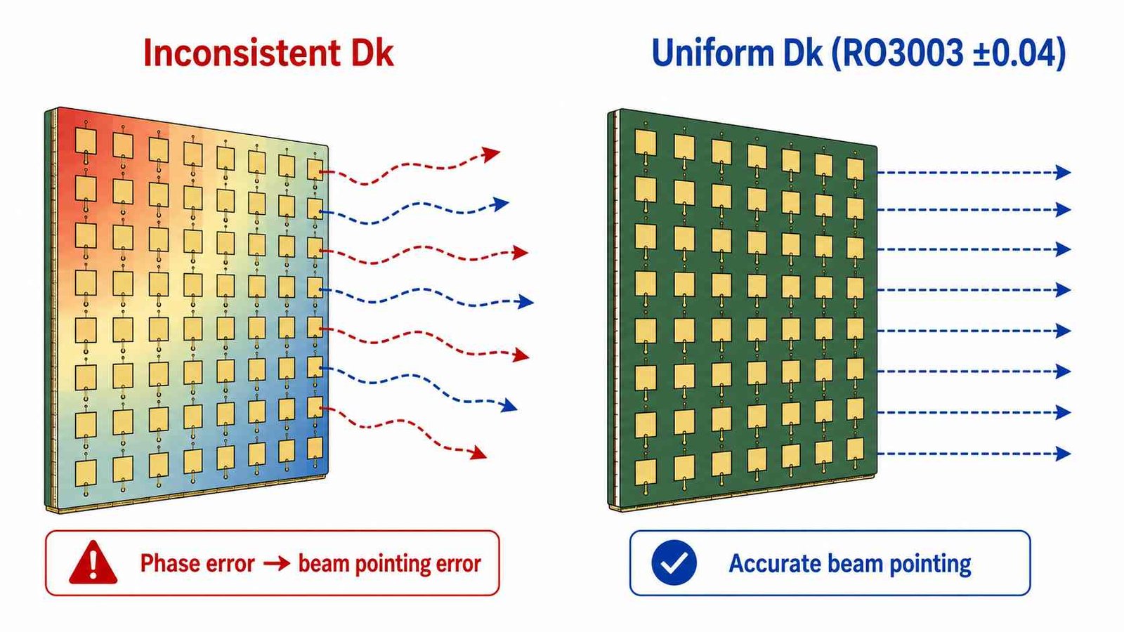
In a phased array, each antenna element’s phase is set by the feed network electrical length, which depends on the substrate Dk. If Dk varies across the panel — even slightly — elements at different positions have slightly different electrical lengths for the same physical trace length. This produces a systematic phase error across the array, which translates directly into beam pointing error.
Rogers RO3003 specifies Dk 3.0 ±0.04 — among the tightest tolerances in the PTFE material range. Combined with controlled manufacturing process (single-lot allocation, max 2 lamination cycles, TDR verification per panel), this minimizes the systematic Dk variation that causes phase error.
Manufacturing Controls for Phase Consistency
| Factor | Why It Matters | Riching PCB Approach |
|---|---|---|
| Panel-level Dk uniformity | Dk variation between elements causes phase error → beam pointing error | RO3003 ±0.04 Dk — tightest in PTFE range |
| Element-to-element impedance match | Impedance mismatch causes amplitude taper error | TDR ±5% measured per panel, report provided |
| Via fence consistency | Inconsistent fence affects element isolation differently per element | 0.4mm center-to-center via spacing — uniform across panel |
| Lamination cycle limit | Repeated press cycles shift Dk non-uniformly across panel | Max 2 cycles enforced — prevents cumulative Dk drift |
| Material lot consistency | Different material lots within one array = systematic phase error | Single-lot material allocation for multi-panel orders — on request |
Applications
| Application | Typical Stackup | Note |
|---|---|---|
| AESA defense radar (X/Ku/Ka band) | RO3003 0.127 / 0.254mm, 4-8L | IPC Class 3, ±5% TDR, full traceability |
| Satcom phased array antenna (Ka-band) | RO3003 0.127mm + RT5880 hybrid | Bondply 2929 at PTFE interfaces |
| 5G mmWave beamforming module | RO3003 / RT5880, 4-6L | Min trace/space 2.5mil for dense routing |
| TR (Transmit/Receive) module array | RO3003 0.127mm, single or dual layer | BGA pads for TR chip — 0.2mm min drill |
| AESA feed network | RO3003 + FR4 hybrid | FR4 inner layers for DC distribution and control |
Process Capabilities for Phased Array PCB
- RO3003 0.127mm and 0.254mm in stock — no material procurement delay
- TDR impedance verification per panel — ±5% tolerance available, report provided
- Single-lot material allocation for multi-panel orders — on request
- Min trace/space 2.5mil / 2.5mil — dense corporate feed network routing
- Min drill 0.2mm mechanical, 0.1mm laser — BGA pads for TR module ICs
- Via fence: 0.4mm center-to-center — uniform element isolation
- Max 2 lamination cycles — prevents cumulative Dk drift across panel
- Hybrid RO3003 + FR4 stackups — Rogers 2929 bondply for DC/control layer integration
- IPC Class 3 on request — full material traceability and lot documentation
How to Order
- WhatsApp: +86 13760473650
- Send: Gerber zip + NC drill + stackup drawing
- Specify: RO3003 thickness, impedance tolerance (±5% recommended), IPC Class, panel quantity
- Note if single-lot material allocation is required for multi-panel arrays
- DFM review: 4–8 hours
Phased Array PCB Manufacturer — Shenzhen Direct Factory
RO3003 In Stock · ±0.04 Dk Tolerance
TDR ±5% Per Panel · IPC Class 3 · No MOQ
Send Gerber + stackup drawing. DFM review within 4–8 hours.
Specify panel quantity and single-lot allocation if required.
DFM review within 4–8 hours
Request a PCB Quote
Upload your Gerber ZIP file and project requirements. Our engineering team will review your PCB material, stackup, impedance needs, surface finish, and production quantity before quoting.
Please prepare:
- Gerber files in ZIP format
- PCB material or stackup requirements
- Controlled impedance notes if available
- Prototype or batch production quantity
