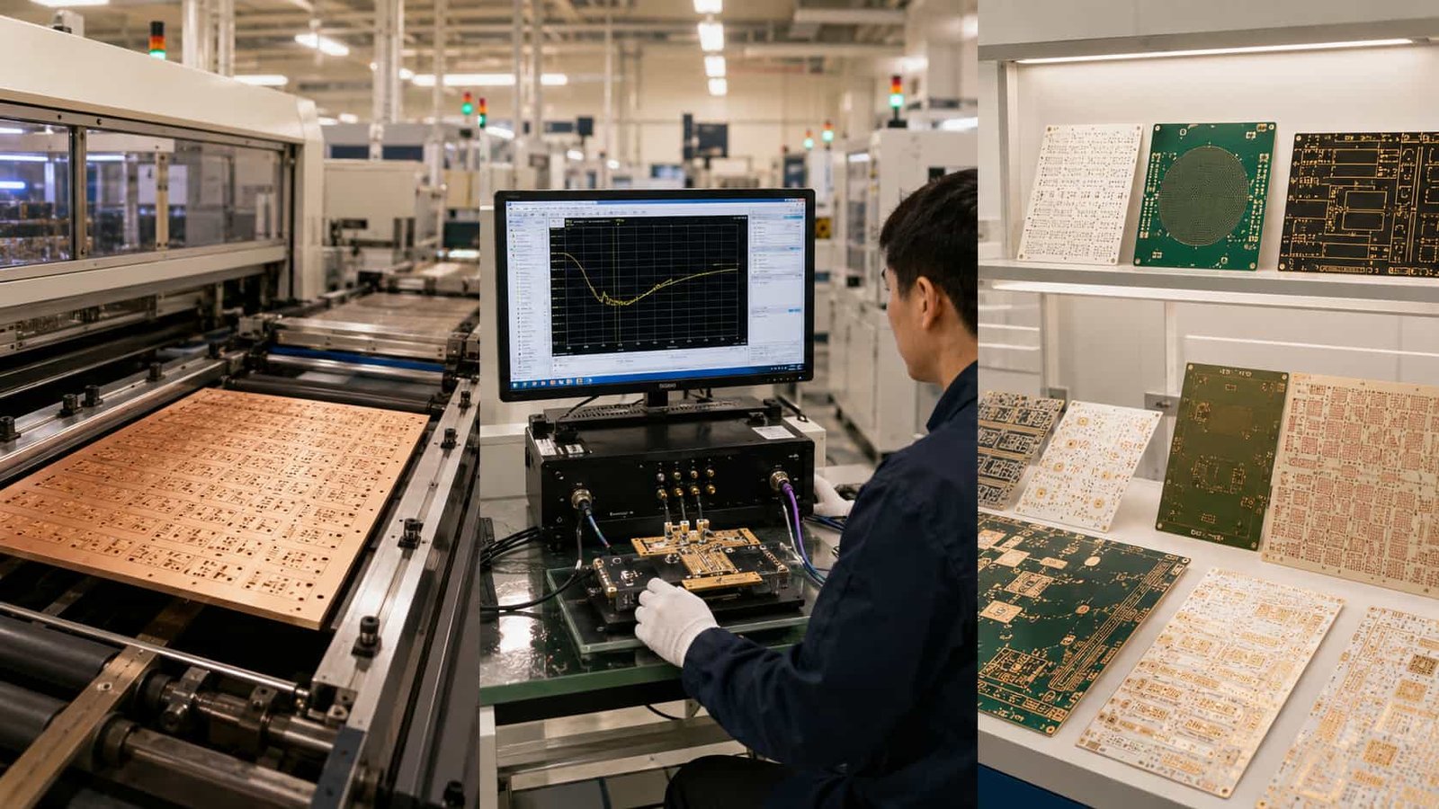
A high frequency PCB is any PCB designed to carry RF or microwave signals — typically above 500 MHz — where the electrical behavior of the PCB material itself becomes a performance variable. Below approximately 500 MHz, standard FR4 is adequate for most applications. Above 1 GHz, FR4’s high dissipation factor (Df ~0.020) causes too much signal loss for most RF circuits, and its unstable dielectric constant (Dk) causes impedance to vary with frequency and temperature.
High frequency PCB solves this by using specialized laminate materials — Rogers, PTFE, Taconic, F4B — with low Df, stable Dk, and consistent mechanical properties. These materials allow the factory to manufacture transmission lines with controlled impedance, verified by TDR on every production lot, that maintain predictable RF performance from the first prototype through years of field operation.
As a direct high frequency PCB factory in Shenzhen, China, we produce Rogers, PTFE, Taconic, F4B, and hybrid PCB for radar, satellite communication, electronic warfare, 5G, automotive radar, aerospace, and commercial RF applications. This guide covers everything needed to understand and specify high frequency PCB correctly.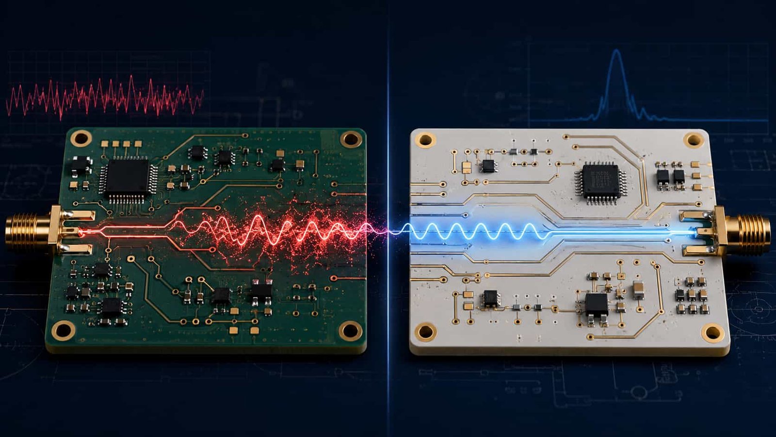
Quick Summary: High Frequency PCB vs Standard FR4
The core difference: Standard FR4 has Df ~0.020 at microwave frequencies — it absorbs approximately 20 times more signal energy per unit length than Rogers RO4350B (Df 0.0037). At 10 GHz over 6 inches of trace, FR4 adds approximately 12 dB of insertion loss. Rogers RO4350B adds approximately 2 dB. Rogers RO3003 (PTFE, Df 0.0010) adds approximately 0.6 dB. For a receiver system, every dB of insertion loss before the LNA adds directly to the system noise figure. For a transmitter, every dB of loss means less power reaches the antenna. High frequency PCB materials exist to keep this loss within the system link budget.
What Makes a PCB ‘High Frequency’
The Two Key Material Properties
Two material properties determine whether a PCB laminate is suitable for high frequency use:
- Dielectric constant (Dk): determines how fast signals travel and how wide 50Ω traces must be. Lower Dk = faster signal velocity, wider traces, easier manufacturing. Higher Dk = smaller circuit elements — useful for compact antenna design. Dk must be stable over frequency, temperature, and humidity.
- Dissipation factor (Df): determines how much signal energy is absorbed by the dielectric as heat. Lower Df = less insertion loss. FR4 Df ~0.020 is acceptable below 500 MHz. Rogers RO4350B Df 0.0037 is the standard for most RF applications. Rogers RO3003 Df 0.0010 is used where minimum loss is critical (Ka-band, EW).
Both properties must be stable — a material with good Dk and Df at room temperature but significant variation with temperature or moisture is not suitable for high frequency PCB in real operating environments.
Controlled Impedance
High frequency PCB is always controlled impedance PCB. The transmission line impedance — determined by trace width, copper thickness, dielectric height, and Dk — must match the source and load impedance (typically 50Ω for single-ended RF) or signal reflections will degrade performance.
- Standard tolerance: ±10% — a 50Ω trace acceptable between 45Ω and 55Ω
- Advanced tolerance: ±8% — for designs with tighter link budget
- Verification: TDR measurement on a coupon on every production panel
- Calculation: uses confirmed production Dk from the material certificate, not nominal values
For detailed controlled impedance guidance, see Controlled Impedance PCB: Design, Calculation and TDR Verification
High Frequency PCB Materials: Selection by Frequency
Rogers RO4350B — The Standard for Most RF Applications (1–12 GHz)
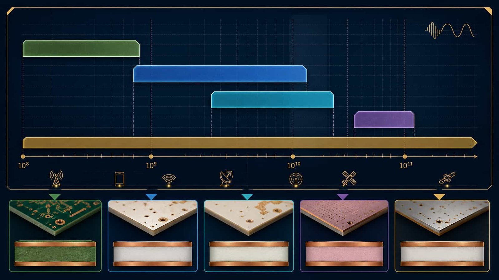
Rogers RO4350B (Dk 3.48, Df 0.0037, Tg >280°C) is the most widely used high frequency PCB material globally. It is a hydrocarbon ceramic material that processes on standard FR4-compatible equipment — no plasma activation, no special bonding film beyond Rogers RO4450F. This combination of adequate RF performance and FR4-compatible manufacturing makes it the default material for most RF PCB designs from L-band through X-band.
- Frequency range: 500 MHz to 12 GHz standard, adequate to 15 GHz for many designs
- Applications: 5G sub-6 GHz, VSAT, S-band surveillance radar, X-band airborne radar, 24 GHz automotive radar, WiFi, wireless infrastructure
- Process: FR4-compatible — no plasma activation, Rogers RO4450F bonding film for hybrids
- Maximum lamination cycles: 3
Full guide: Rogers RO4350B PCB
Rogers RO4003C — X-Band to Ku-Band (8–18 GHz)
Rogers RO4003C (Dk 3.38, Df 0.0027) has 27% lower Df than RO4350B with identical FR4-compatible manufacturing process. It is the correct upgrade when RO4350B’s insertion loss at X-band or Ku-band marginally exceeds the system link budget.
- Frequency range: X-band to Ku-band — most useful above 8 GHz
- Applications: X-band fire control radar with long feed networks, Ku-band VSAT ground terminal
- Cost: approximately 20–35% more than RO4350B
Full guide: Rogers RO4003C PCB
Rogers RO3003 — Ka-Band and 77 GHz (PTFE)
Rogers RO3003 (Dk 3.0, Df 0.0010) is the standard material for Ka-band (26.5–40 GHz) and 77 GHz automotive radar. It is a PTFE ceramic material requiring plasma hole wall activation before copper plating — a completely different manufacturing process from RO4350B.
- Frequency range: Ka-band (26.5–40 GHz), 77 GHz
- Applications: missile seeker, Ka-band AESA radar, 77 GHz automotive ADAS, Ka-band SATCOM
- Process: PTFE — plasma activation mandatory, Rogers 2929 bondply, 2-cycle maximum
Full guide: Rogers RO3003 PCB
Rogers RT5880 — Wideband EW and W-Band (PTFE)
Rogers RT5880 (Dk 2.20, Df 0.0009) has the lowest Df of any standard Rogers material and Dk that varies less than 2% from 1 GHz to 110 GHz. It is the standard material for wideband EW systems covering 2–18 GHz and the only viable material for W-band (75–110 GHz).
- Frequency range: 2–110 GHz — wideband EW and W-band
- Applications: airborne EW receivers, SIGINT, W-band sensing
- Process: PTFE — plasma activation, Rogers 2929 bondply, 2-cycle maximum
Full guide: Rogers RT5880 PCB
Taconic Materials — PTFE Alternative to Rogers
Taconic (now AGC) produces PTFE laminates including TLY-5 (Dk 2.22, Df 0.0009), TLP-5 (Dk 2.20, Df 0.0009), RF-35 (Dk 3.5, Df 0.0018), and CER-10 (Dk 10.0, Df 0.0035). Same PTFE manufacturing requirements as Rogers PTFE materials.
- TLY-5 / TLP-5: equivalent to Rogers RT5880 — EW, wideband applications
- RF-35: Dk 3.5, moderate Df — commercial RF alternative to RO4350B
Full guide: Taconic PCB Materials
F4B — Cost-Effective PTFE for Commercial RF
F4B (Wangling) PTFE materials — including F4BM220 (Dk 2.20, Df 0.0010) — provide comparable RF performance to Rogers at lower cost for commercial applications where Rogers-certified documentation is not required.
Full guide: F4B PCB Materials
ZY (中英) Materials — Chinese PTFE Alternative
- ZYF220D (Dk 2.20, Df 0.0009), ZYF265D (Dk 2.65), ZYF300CA-P (Dk 3.00), ZYF350CA (Dk 3.50)
- Cost-effective alternative to Rogers for commercial Chinese market
Full guide: ZY High Frequency PCB Materials
High Frequency PCB Applications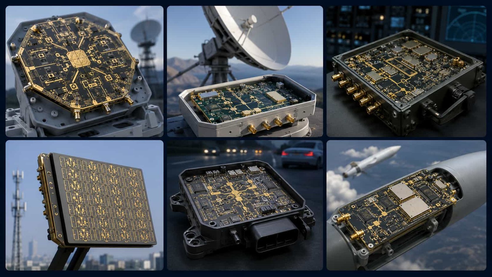
Radar Systems
- S-band surveillance radar (2–4 GHz): Rogers RO4350B — standard material
- X-band fire control radar (8–12 GHz): Rogers RO4350B or RO4003C
- Ka-band radar (26.5–40 GHz): Rogers RO3003 — PTFE required
- 77 GHz automotive radar: Rogers RO3003 or RO3003G2
See: High Frequency PCB for Radar Systems | High Frequency PCB for Automotive Radar
Satellite Communication
- C-band VSAT (4–8 GHz): Rogers RO4350B
- Ku-band VSAT (10.7–14.5 GHz): Rogers RO4003C or RO3003
- Ka-band SATCOM (26.5–40 GHz): Rogers RO3003
See: High Frequency PCB for Satellite Communication
Electronic Warfare and Defense
- EW receivers 2–18 GHz: Rogers RT5880 or Arlon AD250C
- SIGINT collection: Rogers RT5880
- Missile guidance Ka-band: Rogers RO3003, IPC Class 3
- AESA phased array: Rogers RO3003 or RO4350B depending on frequency
See: Rogers PCB for Electronic Warfare | Missile Guidance PCB
5G Communication
- 5G sub-6 GHz massive MIMO: Rogers RO4350B — large panel up to 480×800mm
- 5G mmWave 28/39 GHz: Rogers RO3003, plasma activation required
See: High Frequency PCB for 5G Communication
Aerospace and Avionics
- Airborne communication: Rogers RO4350B, IPC Class 3
- Avionics RF subsystem: Rogers RO4350B or RO4003C
- Wide temperature range: -55°C to +125°C aerospace — Rogers RO3003 for Ka-band
See: High Frequency PCB for Aerospace and Defense | Avionics PCB
Other Applications
Medical Device RF PCB | Industrial IoT PCB | UAV and Unmanned Systems | Naval Shipborne PCB | RF PCB for Wireless Communication Modules
High Frequency PCB Manufacturing: Key Requirements
PTFE Hole Wall Activation
Rogers RO3003, RT5880, Taconic, F4B, and all PTFE-based high frequency materials require plasma or sodium naphthalene hole wall activation before copper plating. Without this step, copper deposits on the PTFE hole wall with no adhesion, passes initial testing, and fails under thermal cycling. This is the single most critical manufacturing step that separates genuine PTFE capability from claimed capability.
How to verify: Ask any high frequency PCB supplier: ‘What hole wall activation method do you use for Rogers RO3003?’ A factory that processes PTFE answers immediately — plasma or sodium naphthalene. A factory that cannot process PTFE gives a vague answer.
Full guide: PTFE PCB Manufacturing Challenges
Stackup Design and Bonding Film
- Rogers RO4350B hybrids: Rogers RO4450F bondply — NOT standard FR4 prepreg
- Rogers PTFE hybrids (RO3003, RT5880): Rogers 2929 bondply — NOT RO4450F
- Maximum lamination cycles: 3 for Rogers hydrocarbon, 2 for all PTFE materials
Full guide: RF PCB Stackup Design
Via Design
- Via stub resonance: back drilling required above 15 GHz, blind via above 26.5 GHz
- Via fence: ground via array for signal isolation — max pitch λ/10 at operating frequency
- Aspect ratio: 10:1 standard, 14:1 advanced
Full guide: Via Design for RF and High Frequency PCB
Surface Finish
- ENIG (standard): nickel 120–300 µin, gold 1–5 µin — most common for high frequency PCB
- ENEPIG: for wire bonding and IPC Class 3 aerospace/defense
- Immersion Silver: preferred above 10 GHz for lowest surface roughness
Full guide: ENIG, ENEPIG and Immersion Silver for RF PCB
Riching PCB: Direct High Frequency PCB Factory
Riching PCB is a direct high frequency PCB manufacturer in Shenzhen, China. We hold Rogers RO4350B, RO4003C, RO3003, RT5880, RO6010, Taconic, F4B, ZY, and Arlon materials in or available for production. Our factory capabilities include:
- PTFE plasma activation: in-house — standard for all PTFE material orders
- Controlled impedance: ±10% standard, ±8% advanced — TDR verified every production lot
- Layer count: 2–32 layers standard, up to 50 layers advanced
- Minimum drill: 0.1mm advanced, 0.2mm standard
- Aspect ratio: 14:1 advanced, 10:1 standard
- IPC Class 3: available for aerospace and defense programs
- No minimum order quantity: prototype from 1 board
- Prototype lead time: 5–7 working days for Rogers RO4350B, 7–10 days for PTFE
- Contact: WhatsApp +86 13760473650 | richingpcb.com
Full factory capability: China High Frequency PCB Manufacturer: Direct Factory