Taconic RF PCB Materials: TLY-5, RF-35, CER-10 Grade Selection Guide
Taconic PTFE material grades, Dk and Df specifications, available thicknesses, Rogers equivalents and manufacturing requirements for RF and microwave PCB.
Home » high frequency PCB material » Taconic RF PCB Materials: TLY-5, RF-35, CER-10 Grade Selection Guide
Table of Contents
Key point: Taconic TLY-5A (Dk 2.17, Df 0.0009) is a direct equivalent to Rogers RT5880 for wideband EW and mmWave applications. Taconic RF-35 (Dk 3.5, Df 0.0018) is a lower-loss alternative to Rogers RO4350B (Df 0.0037). All Taconic PTFE materials require in-house plasma hole wall activation, PTFE-specific drill parameters, and a maximum of 2 lamination press cycles — identical requirements to Rogers PTFE. Riching PCB stocks TLY-5, RF-35 and CER-10 with in-house plasma activation. No MOQ. Prototype lead time 7–10 working days.
Taconic Advanced Dielectric Division produces a full range of PTFE-based RF and microwave PCB substrates that are widely stocked and used as alternatives to Rogers materials. Taconic TLY-5 (Dk 2.17, Df 0.0009) is a direct equivalent to Rogers RT5880 for wideband EW applications; Taconic RF-35 (Dk 3.5, Df 0.0018) is an alternative to Rogers RO4350B with lower Df; and Taconic CER-10 (Dk 10.0, Df 0.0035) is used for high-Dk compact filter and antenna designs.
All Taconic PTFE materials require the same manufacturing processes as Rogers PTFE: in-house plasma hole wall activation before copper plating, PTFE-specific drill parameters, and a maximum of 2 lamination press cycles. This guide covers all major Taconic grades, available thicknesses, how they compare to Rogers equivalents, and manufacturing requirements.
Taconic Grades Overview
| Grade | Dk | Df | Available Thicknesses (mm) | Best Application |
|---|---|---|---|---|
| TLY-5A | 2.17 | 0.0009 | 0.09 / 0.13 / 0.25 / 0.51 / 0.79 / 1.58 / 2.36 | Wideband EW, mmWave, lowest loss |
| TLP-5 | 2.20 | 0.0009 | 0.09 / 0.13 / 0.25 / 0.51 / 0.79 / 1.58 / 2.36 | Wideband EW, RT5880 alternative |
| TLY-5 | 2.22 | 0.0009 | 0.09 / 0.13 / 0.25 / 0.51 / 0.79 / 1.58 / 2.36 | General low-loss PTFE RF |
| TLY-3 | 2.33 | 0.0012 | 0.09 / 0.13 / 0.25 / 0.51 / 0.79 / 1.58 / 2.36 | RT5870 alternative |
| TLT series | 2.45–2.65 | 0.0015–0.0021 | 0.13 / 0.25 / 0.51 / 0.79 / 1.58 / 3.18 | Mid-range Dk PTFE |
| RF-35 | 3.5 | 0.0018 | 0.25 / 0.51 / 0.76 / 1.52 | RO4350B alternative — lower Df |
| RF-60A | 6.5 | 0.0038 | 0.25 / 0.64 / 0.79 / 1.27 / 1.52 / 3.18 | High Dk compact antenna design |
| CER-10 | 10.0 | 0.0035 | 0.28 / 0.64 / 0.76 / 1.19 / 1.58 / 3.18 | Highest Dk — miniaturized filter/antenna |

Taconic vs Rogers: Direct Equivalents
| Taconic Grade | Rogers Equivalent | Dk / Df | Key Difference |
|---|---|---|---|
| TLY-5A / TLP-5 | RT5880 | 2.17–2.20 / 0.0009 | Taconic slightly lower Dk — same loss class |
| TLY-3 | RT5870 | 2.33 / 0.0012 | Near-identical specs — same process |
| RF-35 | RO4350B (approx) | 3.5 / 0.0018 | RF-35 Df 50% lower — but PTFE process required |
| CER-10 | RO3010 | 10.0 / 0.0035 | Similar high-Dk performance |
| RF-60A | RO3006 | 6.5 / 0.0038 | Similar Dk range — verify Df requirement |
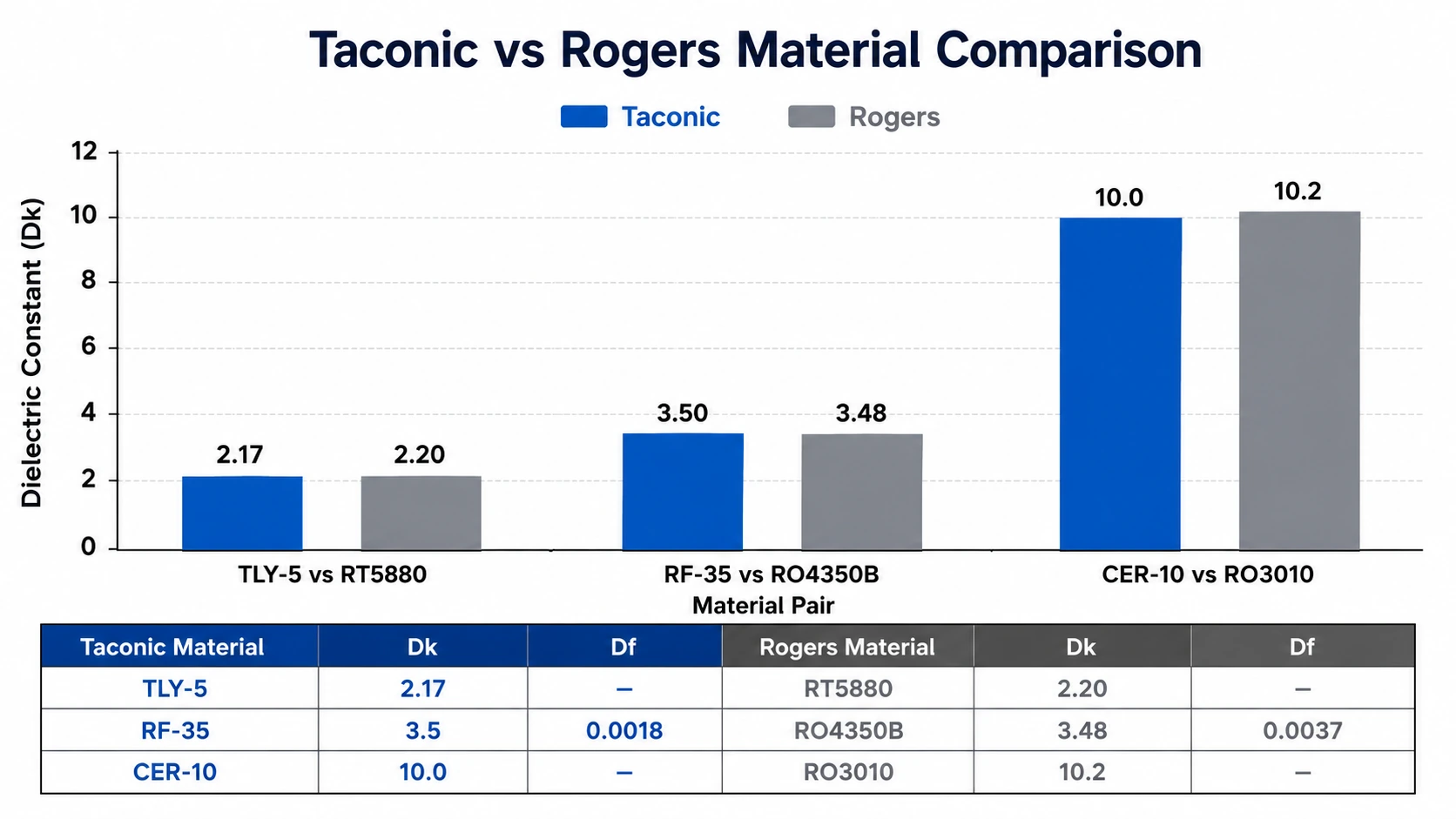
The key practical difference between Taconic and Rogers is availability and pricing, not electrical performance. For most RF designs, Taconic TLY-5 and Rogers RT5880 are interchangeable — the Dk difference of 0.03 (2.17 vs 2.20) produces a trace width difference of less than 2% for the same 50Ω impedance. Confirm material availability before committing to either brand in your design.
Grade-by-Grade Selection Guide
TLY-5A, TLP-5, TLY-5 — Lowest Loss (Dk 2.17–2.22, Df 0.0009)
The TLY-5 family is the Taconic equivalent of Rogers RT5880 — PTFE glass construction with Df 0.0009, suitable for wideband applications from 2 GHz to 40 GHz and above. TLY-5A (Dk 2.17) has the lowest Dk in the range; TLP-5 (Dk 2.20) and TLY-5 (Dk 2.22) are within the same performance class. All three are available in thin substrates down to 0.09 mm — useful for Ka-band and mmWave antenna designs. Use for: wideband EW PCB (2–18 GHz), 5G mmWave PCB (24–40 GHz), Ka-band PCB.
TLY-3 — Dk 2.33, Df 0.0012
TLY-3 is the Taconic equivalent of Rogers RT5870. Slightly higher Dk than TLY-5 gives narrower traces for the same impedance — useful when board area is constrained. Same PTFE glass construction, same plasma activation requirement, same available thicknesses.
TLT Series — Dk 2.45–2.65, Df 0.0015–0.0021
The TLT series covers a mid-range Dk band not well served by Rogers. Useful for designs requiring Dk between 2.33 and 3.0 where RO3003 is too high and RT5870 is too low. Available in a wider thickness range including 3.18 mm for lower frequency applications.
RF-35 — Dk 3.5, Df 0.0018
RF-35 is the most direct Rogers RO4350B alternative in the Taconic range — similar Dk (3.5 vs 3.48) but significantly lower Df (0.0018 vs 0.0037). For designs currently using RO4350B where insertion loss is marginal, switching to RF-35 reduces Df by 50%. Important difference: RF-35 is PTFE-based and requires plasma activation, while RO4350B is hydrocarbon ceramic and does not. Lead time for RF-35 is 7–10 days vs 5–7 days for RO4350B. Available thicknesses: 0.25 / 0.51 / 0.76 / 1.52 mm.
RF-60A — Dk 6.5, Df 0.0038
RF-60A is a high-Dk PTFE material used for compact antenna and filter designs where element miniaturization is the priority. Higher Dk reduces antenna element size proportionally to √Dk — a patch antenna on RF-60A is approximately 40% smaller than on TLY-5. Available thicknesses: 0.25 / 0.64 / 0.79 / 1.27 / 1.52 / 3.18 mm.
CER-10 — Dk 10.0, Df 0.0035
CER-10 is Taconic’s highest-Dk material — ceramic-filled PTFE with Dk 10.0 and Df 0.0035. Used for miniaturized bandpass filters, diplexers, and antenna elements where maximum size reduction is required. At Dk 10.0, patch antenna elements are approximately 55% smaller than on TLY-5. Available thicknesses: 0.28 / 0.64 / 0.76 / 1.19 / 1.58 / 3.18 mm.
Manufacturing Requirements
Plasma Activation — All Taconic PTFE Grades
All Taconic materials listed above are PTFE-based and require in-house plasma or sodium naphthalene hole wall activation before copper plating. This is identical to the requirement for Rogers RO3003 and RT5880. See PTFE PCB manufacturing challenges for full process detail. Riching PCB performs in-house plasma activation on all Taconic orders as standard process.
Lamination Limit
Maximum 2 lamination press cycles for all Taconic PTFE materials — same constraint as Rogers PTFE. For hybrid Taconic + FR4 stackups, use Rogers 4450F or equivalent PTFE-compatible bondply.
Drill Parameters
PTFE-specific drill parameters (reduced spindle speed) apply to all Taconic grades. Standard FR4 drill parameters cause hole wall smearing on PTFE, degrading copper adhesion even after plasma activation.
Impedance Control
±10% standard, ±5% available with TDR verification. Confirm production Dk from material certificate before calculating trace width — Taconic TLY-5 Dk 2.17 produces slightly different trace widths than Rogers RT5880 Dk 2.20. For phased array designs requiring panel-level Dk uniformity, request material lot Dk data from the fabricator.
Applications
- Wideband EW receiver and jammer PCB — TLY-5 / TLP-5 for 2–18 GHz
- 5G mmWave antenna PCB — TLY-5A for 24–40 GHz phased arrays
- Ka-band satellite terminal PCB— TLY-5A or RF-35
- RF bandpass filter PCB — RF-60A or CER-10 for compact filter design
- 77 GHz automotive radar PCB— TLY-5A as RT5880 alternative
- Antenna PCB for patch and slot antennas — full TLY range
Conclusion
Taconic TLY-5 series (Df 0.0009) is the direct equivalent of Rogers RT5880 for wideband and mmWave applications. Taconic RF-35 (Df 0.0018) is a lower-loss alternative to Rogers RO4350B. Taconic CER-10 (Dk 10.0) is used for maximum miniaturization. All Taconic PTFE materials require the same in-house plasma activation and process constraints as Rogers PTFE. Riching PCB stocks TLY-5, RF-35, CER-10, and other Taconic grades with in-house plasma activation, no MOQ, and prototype lead time of 7–10 working days. See high frequency PCB materials overview for the full materials capability.
Get a Quote for Your Taconic RF PCB
TLY-5, RF-35, CER-10 and other Taconic grades in stock. In-house plasma activation. Send the following for DFM review:
- Gerber files + NC drill file
- Taconic material grade and dielectric thickness
- Stackup drawing — copper weight per layer
- Controlled impedance requirements
- Operating frequency and application type
- IPC Class and quantity
WhatsApp +86 13760473650 — DFM review within 24 hours
Taconic RF PCB Materials Q&A
Common questions about Taconic PCB materials including TLY-5 vs RT5880, RF-35 vs RO4350B, CER-10 applications, plasma activation and prototype lead times.
What is Taconic TLY-5 and how does it compare to Rogers RT5880?
TLY-5A (Dk 2.17, Df 0.0009) and TLP-5 (Dk 2.20, Df 0.0009) are direct RT5880 equivalents — same Df, same PTFE glass construction, same manufacturing requirements. Dk difference of 0.03 produces less than 2% trace width difference. Widely used as RT5880 alternative for wideband EW and mmWave.
Is Taconic RF-35 a replacement for Rogers RO4350B?
Similar Dk (3.5 vs 3.48), but RF-35 Df 0.0018 vs RO4350B Df 0.0037 — RF-35 is 50% lower loss. Key difference: RO4350B is hydrocarbon ceramic, FR4-compatible, no plasma needed. RF-35 is PTFE — plasma activation required, 7–10 days lead time vs 5–7 days for RO4350B.
What is Taconic CER-10 used for?
CER-10 (Dk 10.0, Df 0.0035) is for miniaturized RF components — bandpass filters, diplexers, antenna elements where maximum size reduction is needed. At Dk 10.0, elements are ~55% smaller than on TLY-5. Equivalent to Rogers RO3010 (Dk 10.2).
Do Taconic PCB materials require plasma activation?
Yes — all Taconic RF materials (TLY-5, RF-35, CER-10, TLT series) are PTFE-based and require in-house plasma activation before copper plating. Same requirement as Rogers RO3003 and RT5880. Without it, copper fails under thermal cycling. Riching PCB performs in-house plasma activation on all Taconic orders.
What is the prototype lead time for Taconic PCB?
7–10 working days for all Taconic PTFE grades. No MOQ — from 1 board. DFM review before every order. WhatsApp: +86 13760473650 — quotation within 24 hours.
Request a PCB Quote
Upload your Gerber ZIP file and project requirements. Our engineering team will review your PCB material, stackup, impedance needs, surface finish, and production quantity before quoting.
Please prepare:
- Gerber files in ZIP format
- PCB material or stackup requirements
- Controlled impedance notes if available
- Prototype or batch production quantity
